Pixel driving circuit of electro-luminescent display device and driving method thereof

a technology of electro-luminescent display devices and driving circuits, which is applied in the direction of lighting devices, instruments, light sources, etc., can solve the problems of difficult to compensate for variations in election mobility of driving transistors, crosstalk noise may be generated, and the brightness between the upper and lower portions of the display panel may be different, so as to prevent the temperature of the oled panel

Active Publication Date: 2013-11-12
LG DISPLAY CO LTD
View PDF13 Cites 1 Cited by
  • Summary
  • Abstract
  • Description
  • Claims
  • Application Information

AI Technical Summary

Benefits of technology

[0018]An advantage of the present invention is to provide a pixel driving circuit which is capable of preventing the temperature of an OLED panel from increasing or the level of a power supply voltage from dropping below a predetermined value by properly controlling a current supplied from a DC / DC converter towards the OLED panel, and a driving method thereof.

Problems solved by technology

However, the voltage-driven technique has drawbacks in that the brightness between the upper and lower portions of a display panel may be different due to a drop in a pixel power supply voltage, and also crosstalk noise may be generated.
Even though non-uniformity of a threshold voltage is in the driving transistor may be compensated to a certain degree, it is difficult to compensate for variations in election mobility in the driving transistors.
But, it is difficult to drive a current within a short row line time because a data line presents a large parasitic load upon application of a current having a low gradation.
The pixel driving circuit of the electro-luminescent display device in accordance with the related art has a problem in that the current supplied to the OLED panel is not properly controlled.
Accordingly, the temperature increases and the power supply voltage drops below a predetermined level that causes the OLED panel not to operate properly that results in a deteriorated image quality.

Method used


Image

  • Pixel driving circuit of electro-luminescent display device and driving method thereof
  • Pixel driving circuit of electro-luminescent display device and driving method thereof
  • Pixel driving circuit of electro-luminescent display device and driving method thereof

Examples


Embodiment Construction

[0029]Hereinafter, description will be given in detail of the preferred embodiments of the present invention, in conjunction with the accompanying drawings.

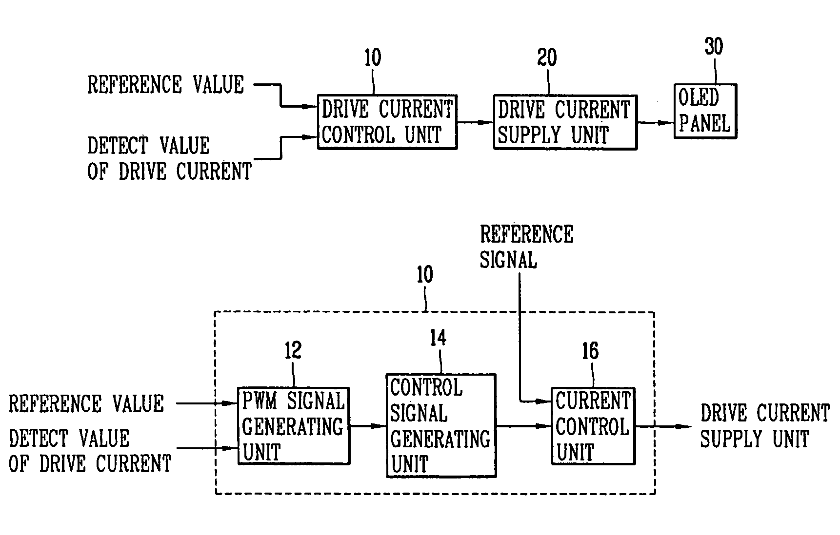
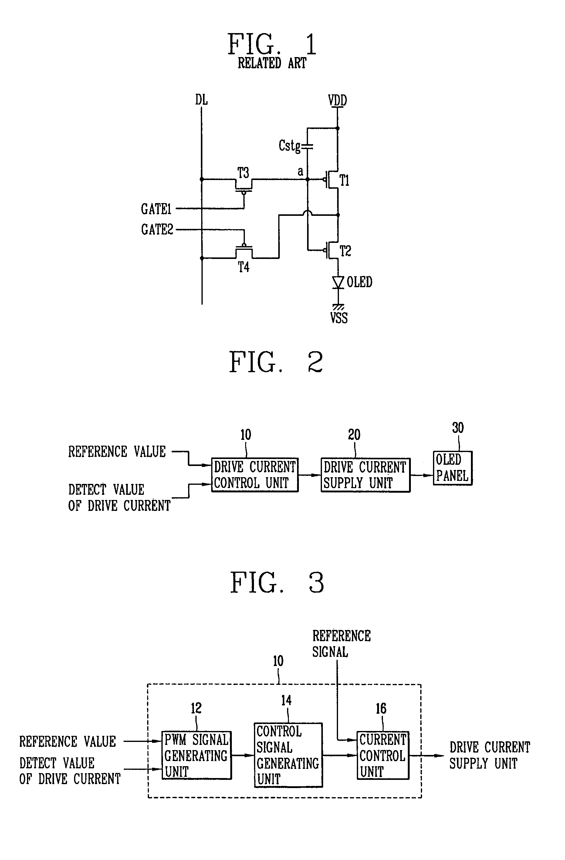
[0030]FIG. 2 is a block diagram of the electro-luminescent display device in accordance with the present invention.

[0031]As shown in FIG. 2, the electro-luminescent display device according to the present invention includes an OLED panel 30, a drive current control unit 10 for detecting the drive current supplied to the OLED panel and controlling the current to be applied to the OLED panel 30 based on the detected current, and a drive current supply unit 20 for supplying the drive current to the OLED panel 30 by the control signal of the drive current control unit 10.

[0032]A plurality of gate lines and data lines are disposed in the OLED panel 30 to define a plurality of pixels and first and second thin film transistors are disposed in each pixel. The first thin film transistor includes a gate electrode connected to the gate line...


PUM


Abstract

The present invention relates to a method for properly controlling the drive current when driving an Active Matrix OLED (AMOLED) in order to prevent the brightness from being changed due to temperature changes in a panel or the performance deterioration of the OLED. The present invention comprises: an OLED (organic light emitting diode) panel that displays an image; pixel driving circuit including: a drive current control unit that outputs a current control signal corresponding to a detected current supplied to the OLED panel; and a comparator that compares the current control signal with a power supply voltage and outputs a bias voltage; and a transistor that receives the power supply voltage and that supplies a drive current to the OLED panel corresponding to the bias voltage.

Description

[0001]This present application claims the benefit of Korean Patent Application No. 10-2006-0119368 filed Nov. 29, 2006, which is hereby incorporated by reference for all purposes as if fully set forth herein.BACKGROUND OF THE INVENTION[0002]1. Field of the Invention[0003]The present invention relates to a driving method of an AM-OLED (Active Matrix Organic Light Emitting Diode) panel, and more particularly, to a pixel driving circuit of an electro-luminescent display device that is capable of preventing changes in brightness due to temperature changes in the panel or a performance deterioration of the OLED and a driving method thereof.[0004]2. Discussion of the Related Art[0005]Generally, pixel structures for AM-OLED displays may be broadly classified into voltage-driven pixels, current-driven pixels and digitally-driven pixels according to their driving method.[0006]The voltage-driven pixel has a structure such that a voltage may be driven at a high speed that is similar to a TFT-L...

Claims


Application Information

Patent Timeline
Patent Type & Authority Patents(United States)
IPC IPC(8): G09G3/30
CPCG09G3/3216G09G3/3233G09G2320/0233G09G2320/029G09G2320/041G09G2320/043G09G2320/0626G09G2330/021G09G3/20G09G3/30G09G3/32H05B33/14
Inventor KIM, IN-HWANBYUN, SEUNG-CHANKIM, JIN-HYOUNG
Owner LG DISPLAY CO LTD
Why Eureka
Try Eureka