

Motor having figure 8-shaped linked coils and method for manufacturing the same
a technology of linked coils and motors, which is applied in the field of motors, can solve the problems of deteriorating the levels of cogging torque and torque ripple, limited advantageous effects in even fractional slot configuration, and complicated layout of windings, so as to increase the number of production steps and the number of coils.
- Summary
- Abstract
- Description
- Claims
- Application Information
AI Technical Summary
Benefits of technology
Problems solved by technology
Method used
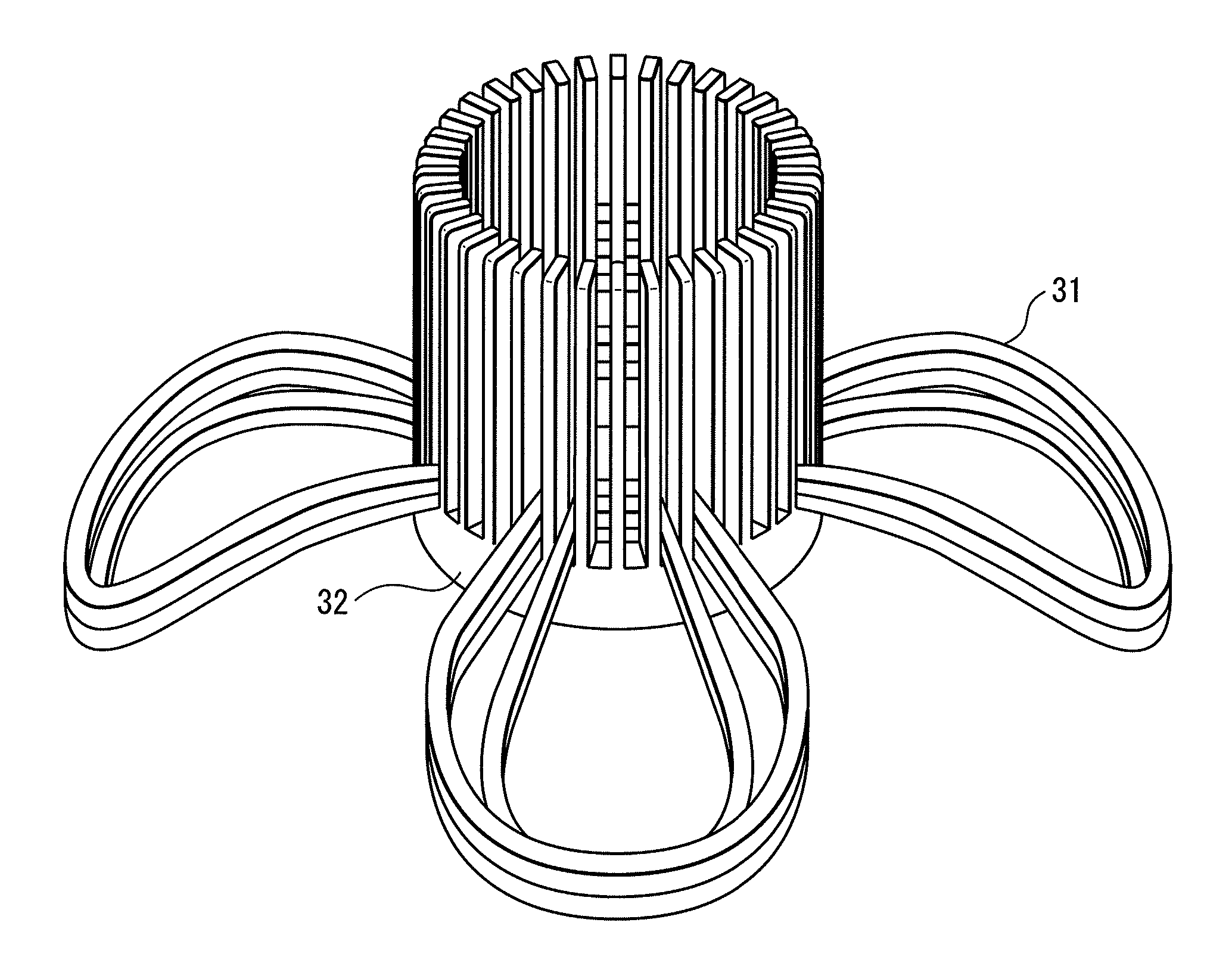
Image

Examples
first embodiment
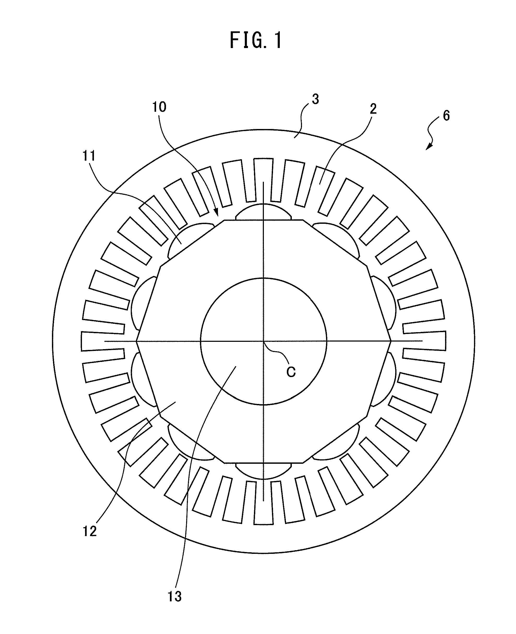
[0047]A three-phase alternating current (AC) motor according to a first embodiment of the present invention is described. FIG. 1 illustrates a cross-sectional view of a 10-pole 36-slot motor. In FIG. 1, 6 denotes a stator and 10 denotes a rotor. The rotor 10 includes ten magnets 11, a rotor core 12, and a shaft 13 of the rotor, and the rotor 10 rotates about a rotation axis C of the rotor. The number of magnetic poles P is ten, which is the same as the number of the magnets. The stator 6 includes a stator core 3, and thirty six slots 2 formed in the direction of the rotation axis C of the rotor and circumferentially arrayed, and windings to be described later are arranged in the slots 2. The present invention relates to the layout of the windings wound around the stator core 3 in the motor, and therefore the description of the rotor will be omitted in the following.
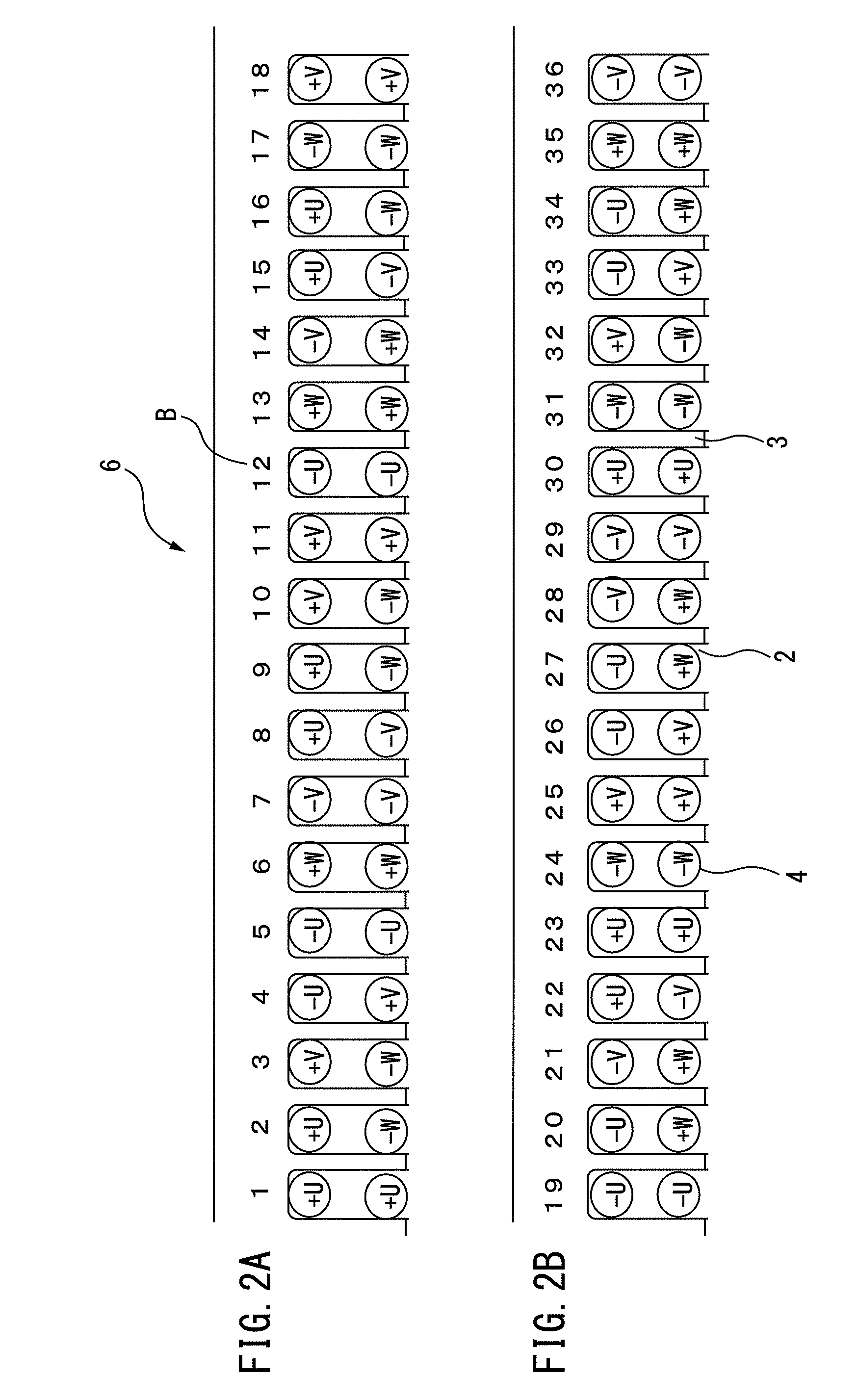
[0048]FIG. 2 is a view illustrating a layout of coils of each phase in the slots in a fractional slot type motor with t...
second embodiment
[0068]Next, a three-phase AC motor according to a second embodiment of the present invention is described. FIG. 11A and FIG. 11B illustrate a 10-pole 36-slot 3-layer winding layout (three phases arranged for each slot) of the three-phase AC motor according to the second embodiment of the present invention. The three-phase AC motor according to the second embodiment of the present invention is different from the three-phase AC motor according to the first embodiment in terms of the fact that in a plurality of sets out of the N sets per phase of figure 8-shaped linked coils, one coil out of the linked two coils has a number of windings different from that of another coil. Since other configurations of the three-phase AC motor according to the second embodiment of the present invention are the same as the configurations of the three-phase AC motor according to the first embodiment of the present invention, the detailed description will be omitted.
[0069]In the developed view of the coil...
third embodiment
[0079]Next, a method for manufacturing a three-phase AC motor according to a third embodiment of the present invention is described. The method for manufacturing a three-phase AC motor according to the third embodiment of the present invention is a method for manufacturing a three-phase AC motor including figure 8-shaped linked coils by using an inserter type automatic winding machine that is equipped with a nozzle rotating while releasing windings and has two or more parallel winding frames around which the windings are wound to produce coils, the method including a first step of adjusting heights of the two winding frames and rotating the nozzle around one of the winding frames by a predetermined number of windings to produce a first coil, a second step of adjusting the heights of the two winding frames and rotating the nozzle around another of the winding frames by a predetermined number of windings in a direction opposite to the rotation direction to produce a second coil having...
PUM
 Abstract
Description
Claims
Application Information