Microtubes for therapeutic delivery

a microtube and therapeutic technology, applied in the direction of prosthesis, catheter, soldering apparatus, etc., can solve the problems of inability to achieve uniform dosage of therapeutic from the coating of the stent to its surroundings, and compromise the effectiveness of the sten

Inactive Publication Date: 2007-01-30
BOSTON SCI SCIMED INC
View PDF11 Cites 14 Cited by
  • Summary
  • Abstract
  • Description
  • Claims
  • Application Information

AI Technical Summary

Problems solved by technology

When this coating is haphazardly applied or has somehow been removed during the stent's manufacture or delivery the stent's effectiven

Method used


Image

  • Microtubes for therapeutic delivery
  • Microtubes for therapeutic delivery
  • Microtubes for therapeutic delivery

Examples


Embodiment Construction

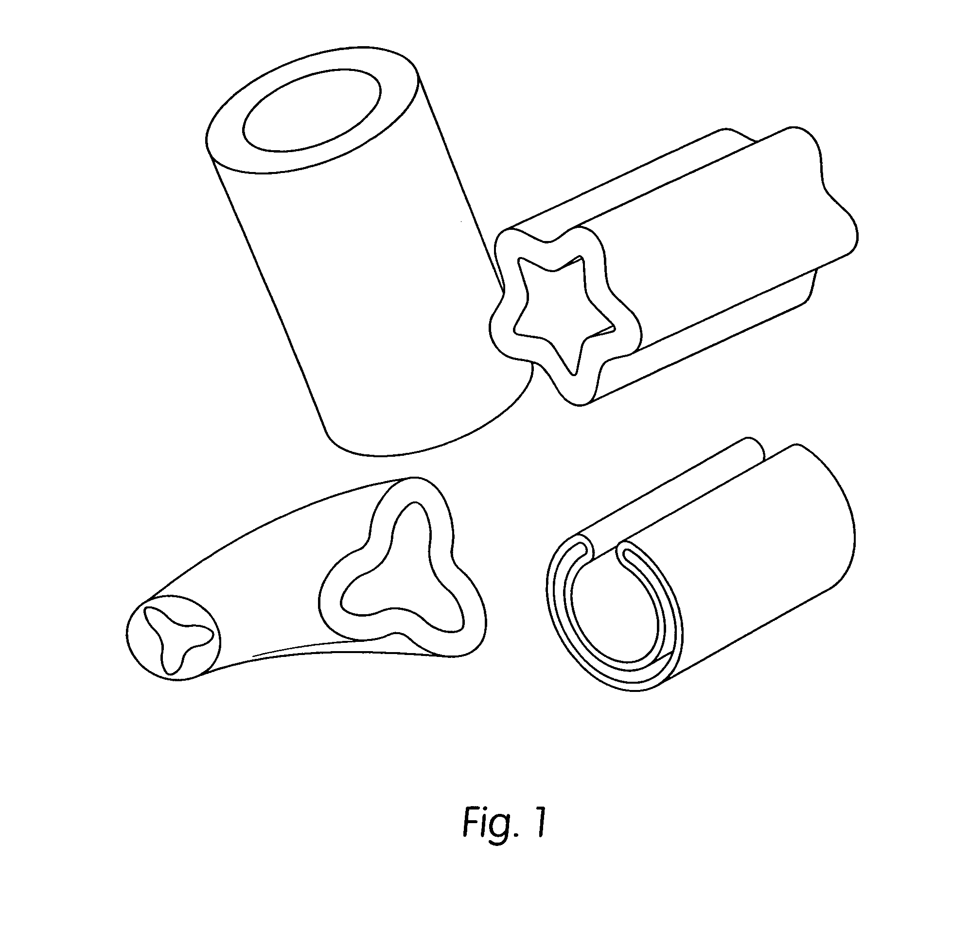
[0017]FIG. 1 provides an illustration of an enlarged cross-sectional view of several different microtubes as may be used in various embodiments of the present invention. As can be seen in FIG. 1, microtubes may be sized to be smaller than a human hair, being a few tens of microns in diameter, and may be constructed with various cross-sectional configurations, including U-, Y-, star-, and oval-shaped cross-sections. The microtubes may be hollow closed vessels, sleeves having one or more open ends, and solid structures. The microtubes in FIG. 1 are illustrated as being hollow with at least one open end. The microtubes may be made from a number of materials including metals, ceramics, and hard carbon. One advantage of employing microtubes in accord with the present invention is the increased surface area associated with their use.

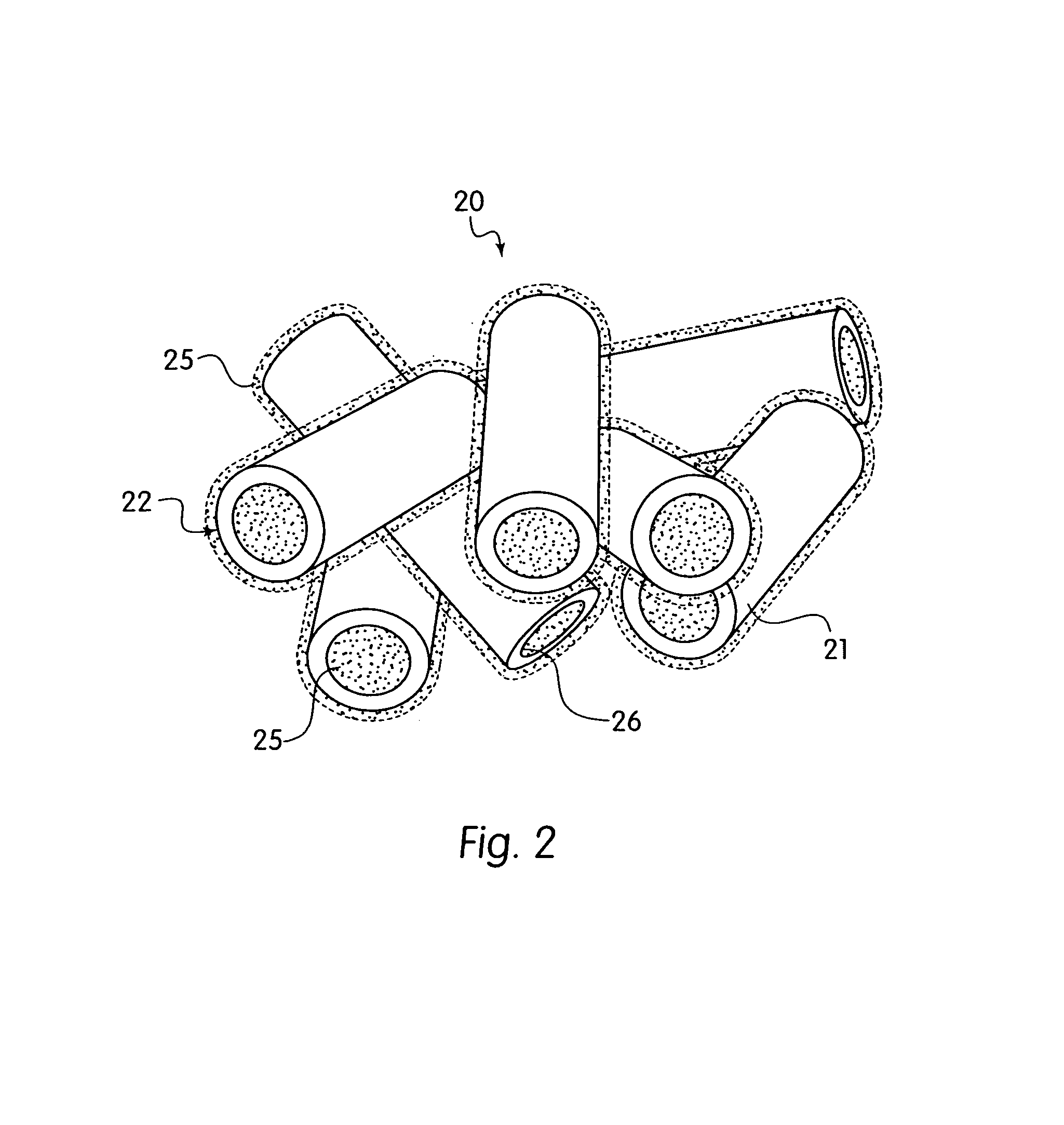
[0018]FIG. 2 provides an enlarged view of a pliant stratum 20 of microtubes 21 having a therapeutic 25 coating both the inner 26 and outer 22 surfaces of micr...


PUM

PropertyMeasurementUnit
Forceaaaaaaaaaa
Lengthaaaaaaaaaa
Therapeuticaaaaaaaaaa

Abstract

A medical implant that delivers therapeutic via microtubes and a method of making the same is provided. In one embodiment a biologically implantable structure adapted to fit within the body of a patient is provided. This structure may have a plurality of individual microtubes in physical communication with its outer surface, the microtubes containing or carrying a therapeutic. In an alternative embodiment a method of manufacturing an implantable medical appliance is provided. This method includes placing a pliant stratum of microtubes onto a biologically implantable medical structure and then applying a therapeutic to the pliant stratum to cover or fill the microtubes.

Description

TECHNICAL FIELD[0001]The present invention regards the delivery of therapeutic to a target site. More specifically, the present invention regards the use of therapeutic laden microtubes, implanted near or at a target site, to deliver therapeutic to a target site of a patient.BACKGROUND[0002]The delivery of therapeutic to a target site is an oft-repeated procedure in the practice of contemporary medicine. Therapeutic may be delivered to a target site through direct injection as well as through implants that somehow carry the therapeutic. Implants that are used to deliver therapeutic may serve several purposes including reinforcing fatigued lumens and bridging ruptured vessels. In each of these cases the therapeutic being delivered may not only facilitate the short term healing associated with the introduction of the implant, but may, also, provide long term delivery of therapeutic to the surrounding areas.[0003]One example of an implant is an expandable stent. Expandable stents are t...

Claims


Application Information

Patent Timeline
IPC IPC(8): B21D39/04A61L29/00A61F2/82A61F2/84A61K9/22A61L26/00A61L27/50A61L27/54A61L29/14A61L29/16A61L31/00A61L31/14A61L31/16
CPCA61L26/0061A61L26/0066A61L27/50A61L27/54A61L29/16A61L31/14A61L31/16A61L29/14A61L2300/622
Inventor WALAK, STEVEN
Owner BOSTON SCI SCIMED INC
Why Eureka
Try Eureka