[0019]With this throw-away tipped drill, due to the formation of the slit which extends from the bottom surface of the tip attachment seat towards the rear end, when the end portion of the drill which is divided into two by the tip attachment seat is elastically deformed so that the pair of internal side surfaces of the tip attachment seat mutually approach towards one another, the amount of flexing of each of the two end portions of the drill which are thus divided is increased, and the pressing force when pressing the pair of outer side surfaces of the tip with the pair of internal side surfaces of the tip attachment seat is increased.
[0020]Furthermore since the slit is arranged so as to be displaced closer, among the end portions of the drill main body which is divided into two by the tip attachment seat, towards that one of those end portions into which the shaft portion of the clamp bolt is screwingly engaged, than towards that one of those end portions which is pressed by the head portion of the clamp bolt, thereby, when the slit is thus narrowed, a difference is created in the cross sectional area of the drill main body which is positioned on both sides, and the end portion on the side which is pressed by the head portion of the clamp bolt is harder to flex than the end portion on the side into which the shaft portion of the clamp bolt is screwingly engaged. Accordingly, it becomes easy to set the flexing of the end portion on the side which is pressed by the head portion of the clamp bolt, which is basically harder to flex, and the flexing of the end portion on the side into which the shaft portion of the clamp bolt is screwingly engaged, which is basically easier to flex, to be approximately mutually equal to one another, and thereby it becomes possible to arrange for the pressing forces, when the pair of outer side surfaces of the tip are pressed by the pair of internal side surfaces of the tip attachment seat which are positioned on the drill main body which is divided into two portions, to be approximately mutually equal to one another. As a result, along with it becoming possible to clamp the tip very strongly, it is also possible to maintain the accuracy of deflection of its
cutting edge at an appropriate level.
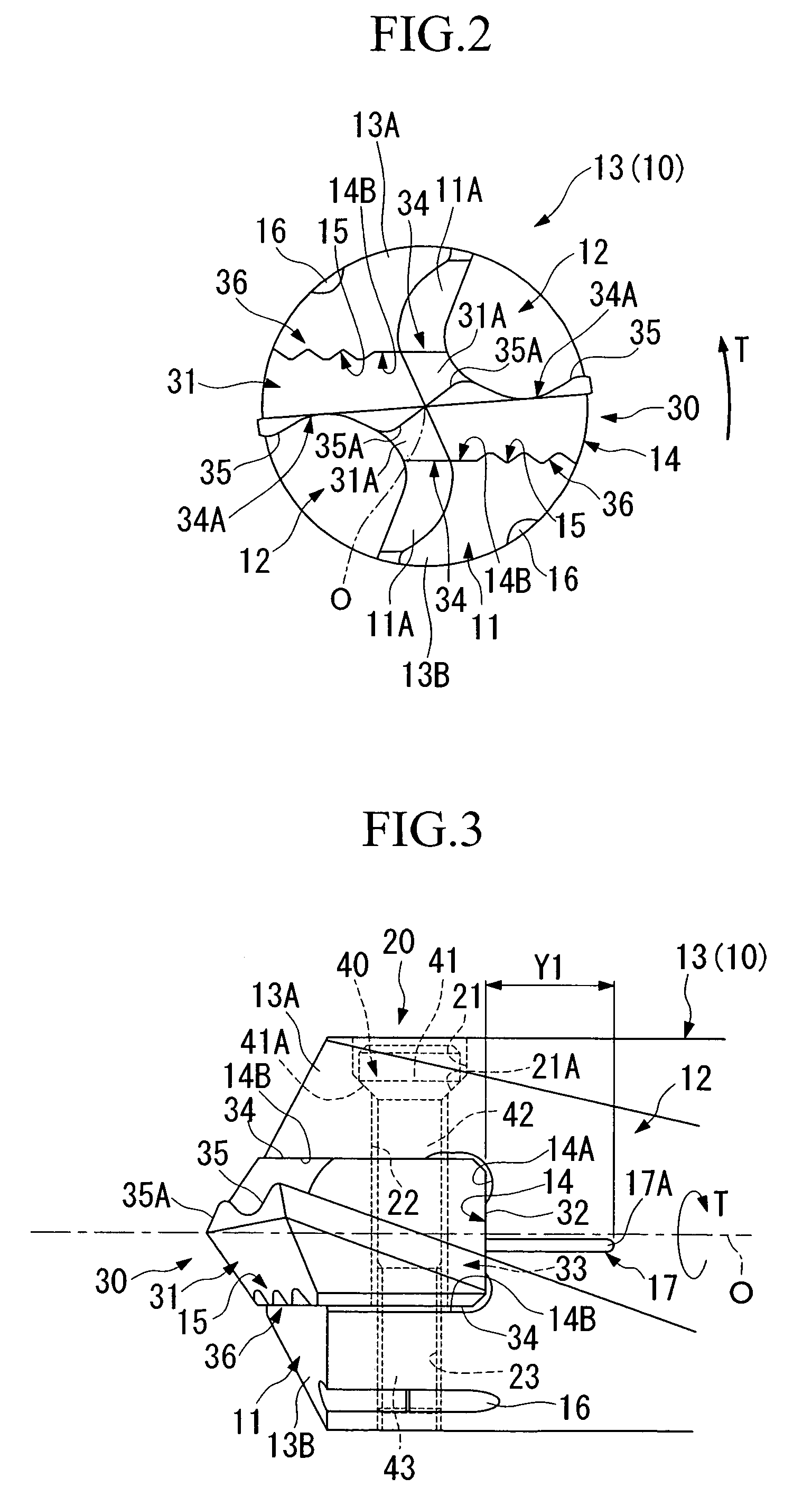
[0023]With this throw-away tipped drill, the end portion of the drill main body which is divided into two by the tip attachment seat is elastically deformed so as to be pressed inwards by the tightening force of the clamp bolt, and clamps the outer side surface of the tip which is fitted into the tip attachment seat. At this time, since the inclined portion is provided which extends towards the outside of the thickness direction from the edge side facing along towards the rear end in the region of the outer side surface of the tip which is engaged to the tip attachment seat, accordingly the tip attachment seat comes to be in a state in which its edge side juts out more to the inside than to the rear end side. In other words, in this state, the tip attachment seat is elastically deformed into a shape which follows along the inclined portion which is provided upon the outer side surface of the tip, and becomes shaped in a concave groove shape which tapers off as seen from the side. As a result, displacement of the tip towards the edge of the drill main body is restrained, and falling off of the tip from the drill main body is reliably prevented.
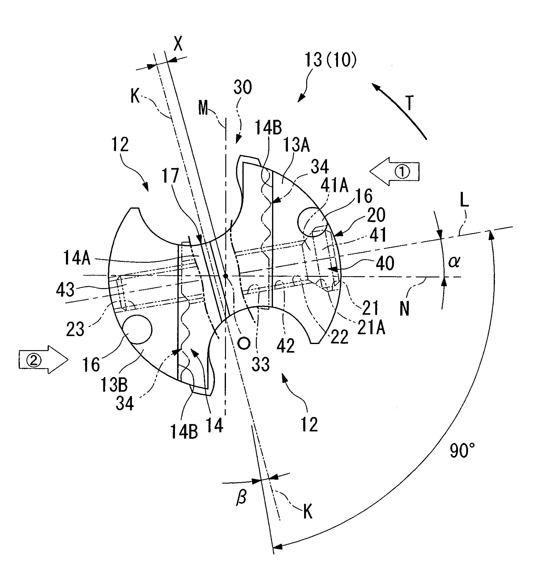
[0026]With this throw-away tipped drill, when the tip has been fitted to the tip attachment seat by clamping the pair of outer side surfaces of the tip with the pair of internal side surfaces of the tip attachment seat which are mutually brought towards one another by the tightening of the clamp bolt, the pressure portions which are provided upon the internal side surfaces of the tip attachment seat by the formation of the concave portions are pressed against the outer side surfaces of the tip so as to rotate the tip around the axial line facing towards the backward direction of the rotational direction of the drill. Accordingly, even though the pair of raked surfaces of the tip are opened towards the respective ones of the pair of
chip disposal grooves, it does not happen that the tip, when fitted to the tip attachment seat, juts out so as to be rotated around the axial line towards the forward direction of the rotational direction of the drill, which would be undesirable. As a result, the portions of the pair of outer side surfaces of the tip which face towards the reverse direction of the rotational direction of the drill are reliably strongly held against the portions of the pair of internal side surfaces of the tip attachment seat which face towards the forward direction of the rotational direction of the drill, and it becomes possible to fit the tip to the tip attachment seat in a strongly fixed manner.
[0028]Moreover, with this throw-away tipped drill, a serrated construction is constituted by the convex portions on the tip and the guide grooves on the tip attachment seat which are mutually engaged together. Furthermore, as described above, since the portions of the tip on its pair of outer side surfaces facing the rearward direction of the rotational direction of the drill and the portions of the tip attachment seat on its pair of internal side surfaces facing the forward direction of the rotational direction of the drill are reliably kept in
close contact with one another, accordingly it is possible reliably to keep the convex portions and the guide grooves which are formed upon these portions in
close contact with one another without any gaps being opened up between them. As a result, it is possible to enhance the accuracy of position determination of the tip with respect to the main body of the drill.
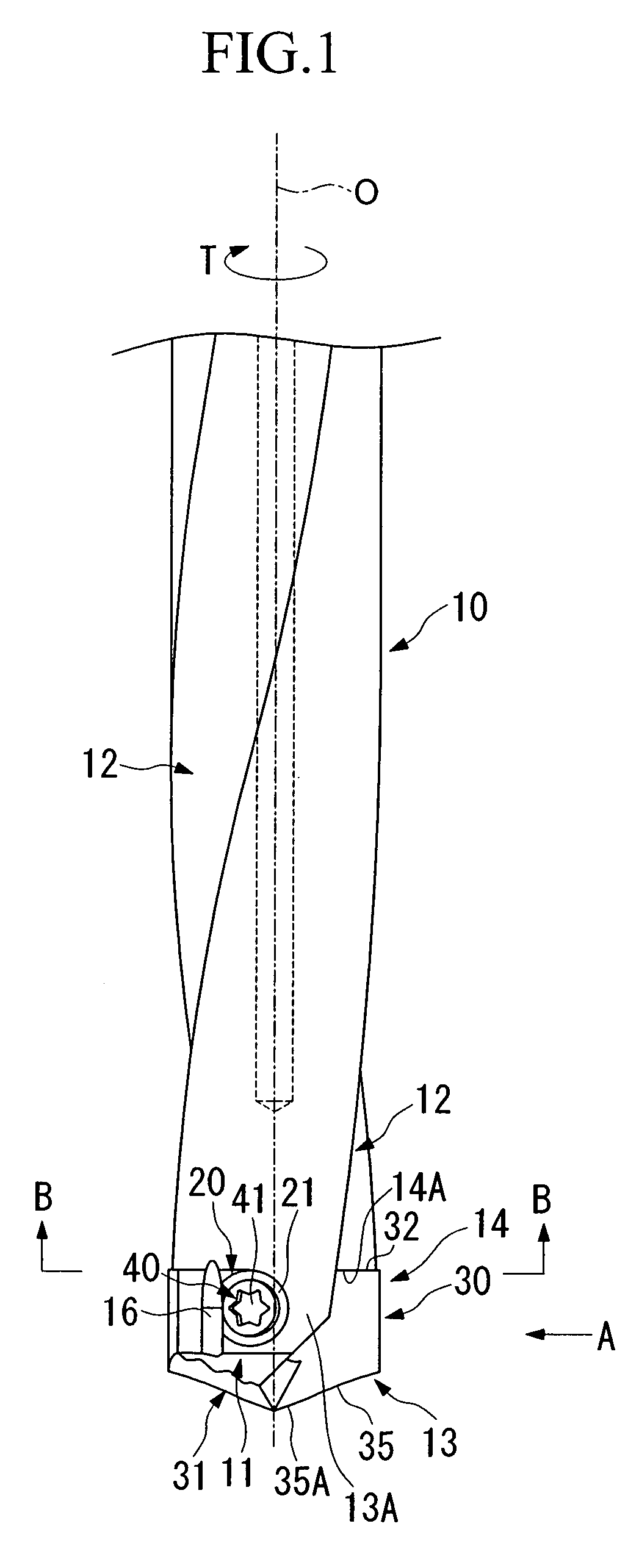
[0033]With this drill main body, by forming the slit upon the bottom surface of the tip attachment seat of the drill main body, elastic deformation of the end portion of the drill main body becomes easy, so that it is possible easily and reliably to perform fitting of the tip to the drill main body.

