Occupant restraint system

a technology for occupants and seats, applied in the direction of pedestrian/occupant safety arrangements, vehicular safety arrangements, transportation and packaging, etc., can solve the problems of uneven dimension of gap between seats, and increased or decreased gap, so as to improve the appearance of connecting parts and smoothly guide the deployment of airbags without increasing the number of components

Active Publication Date: 2007-02-06
HONDA MOTOR CO LTD
View PDF9 Cites 25 Cited by
  • Summary
  • Abstract
  • Description
  • Claims
  • Application Information

AI Technical Summary

Benefits of technology

[0008]The present invention is made in view of the above-described circumstances, and has an object to improve appearance of a connecting portion between a roof lining and a center pillar garnish, and to smoothly guide a deploying airbag without increasing the number of components.
[0010]According to the above-described construction, the end edge of the roof lining is engaged in the roof lining engaging groove extending along the side surface of the upper end portion of the pillar garnish which is at the side of the pillar, and therefore a gap in the connecting portion between the pillar garnish and the roof lining is eliminated to improve the appearance. The airbag deployment guide wall extends to the outside of the vehicle compartment from the upper end of the roof lining engaging groove at the side of the pillar, and the airbag module is disposed at the position sandwiched by the pillar and the roof lining, above the airbag deployment guide wall. Therefore, the inflating airbag is guided toward the vehicle compartment so as not to be caught by the upper end of the pillar garnish, and can be deployed into the vehicle compartment by reliably pressing to open the roof lining, without providing a special guide member. In addition, the locking projection extending upward from the end portion of the airbag deployment guide wall of the pillar garnish at the outside of the vehicle compartment is engaged in the engaging hole formed in the pillar, and therefore assembling of the pillar garnish is facilitated.
[0012]According to the above-described construction, the rib provided at the inner surface of the roof lining engaging groove, which is near the pillar, bites into the end edge of the roof lining, and therefore the end edge of the roof lining is pressed against the inner surface of the roof lining engaging groove, which is near the vehicle compartment, with the reaction force from the rib to eliminate a gap, thus further improving the appearance of the connecting portion between the pillar garnish and the roof lining.
[0016]According to the above-described construction, the position of the end edge of the roof lining at the room temperature is within the first predetermined distance upward from the upper end of the rib in the bottom wall of the roof lining engaging groove, and therefore even if the roof lining expands by heat due to the temperature rising higher than the room temperature, the heat expansion of the roof lining can be absorbed by the first predetermined distance. Even if the temperature rises further, the heat expansion can be absorbed by causing the rib on the bottom wall of the roof lining engaging groove bite into the end edge of the roof lining. On the other hand, if the temperature decreases to be lower than the room temperature and the roof lining thermally contracts, the end edge of the roof lining can be prevented from falling off from the roof lining engaging groove by the second predetermined distance.
[0018]According to the above-described construction, the rib is projectingly provided at the pillar garnish below the roof lining engaging groove to abut to the pillar, and therefore the pillar garnish is biased to the vehicle compartment with respect to the pillar by the rib to reliably engage the locking projection provided at the upper end of the pillar garnish in the locking hole of the pillar so as not to cause rattling.
[0020]According to the above-described construction, the locking projection of the pillar garnish is engaged with the upper edge of the engaging hole of the pillar, and therefore the pillar garnish is positioned in the vertical direction to further improve the appearance of the connecting portion with the roof lining without requiring a special positioning member.

Problems solved by technology

However, in each of the above-described inventions described in Japanese Patent Application Laid-open Nos. 2001-122073 and 2002-362287, the connecting portions of the roof lining and the center pillar garnish only butt to each other in the vertical direction, and therefore there arises the problem that the dimension of the gap between them is not stabilized to make the appearance worse.
Especially when the roof lining and the center pillar garnish expand or contract due to temperature difference, the gap is increased or decreased, and the appearance is further worsened.

Method used


Image

  • Occupant restraint system
  • Occupant restraint system
  • Occupant restraint system

Examples


first embodiment

[0034]the present invention will be described below based on FIG. 1 to FIG. 4.

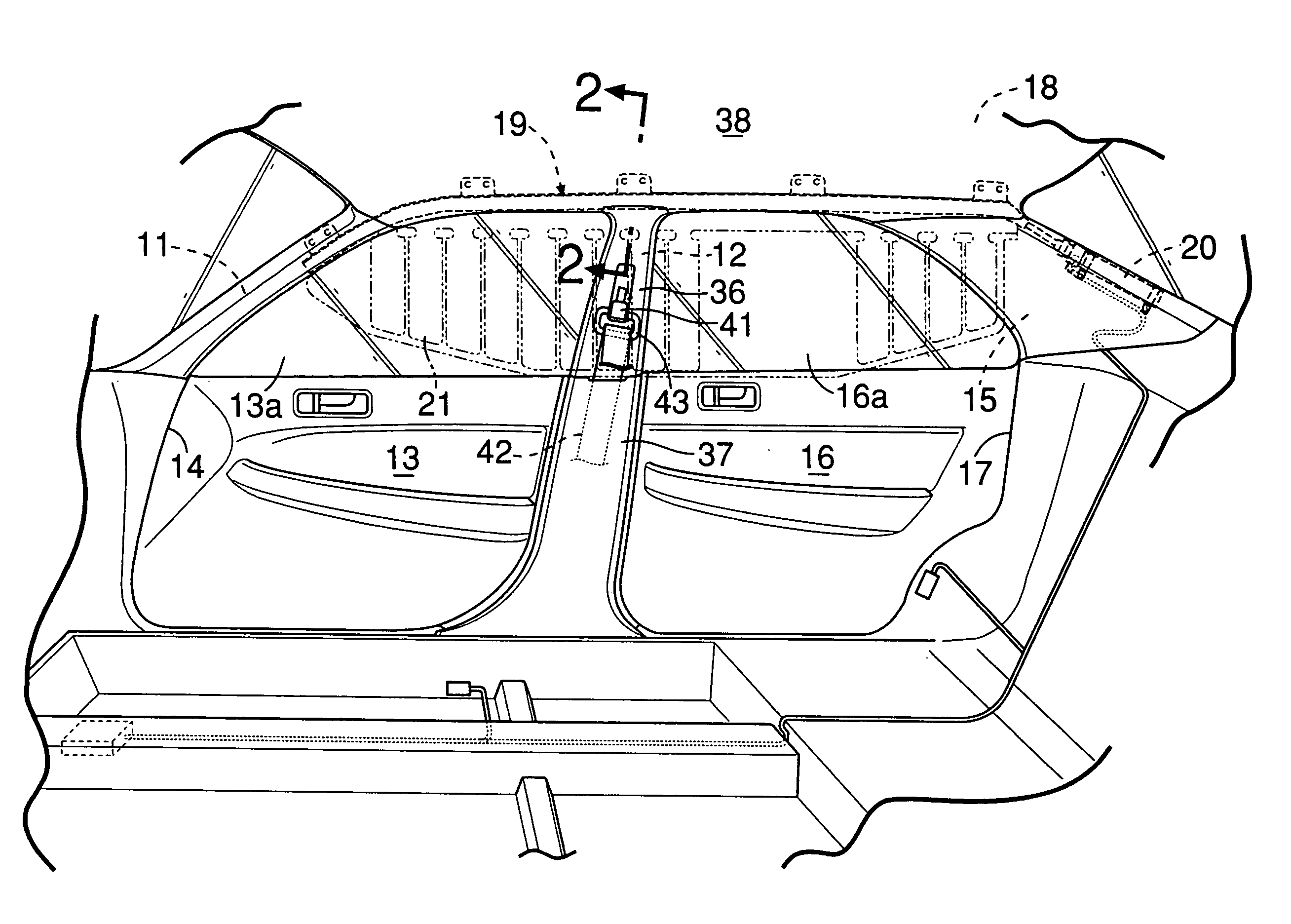
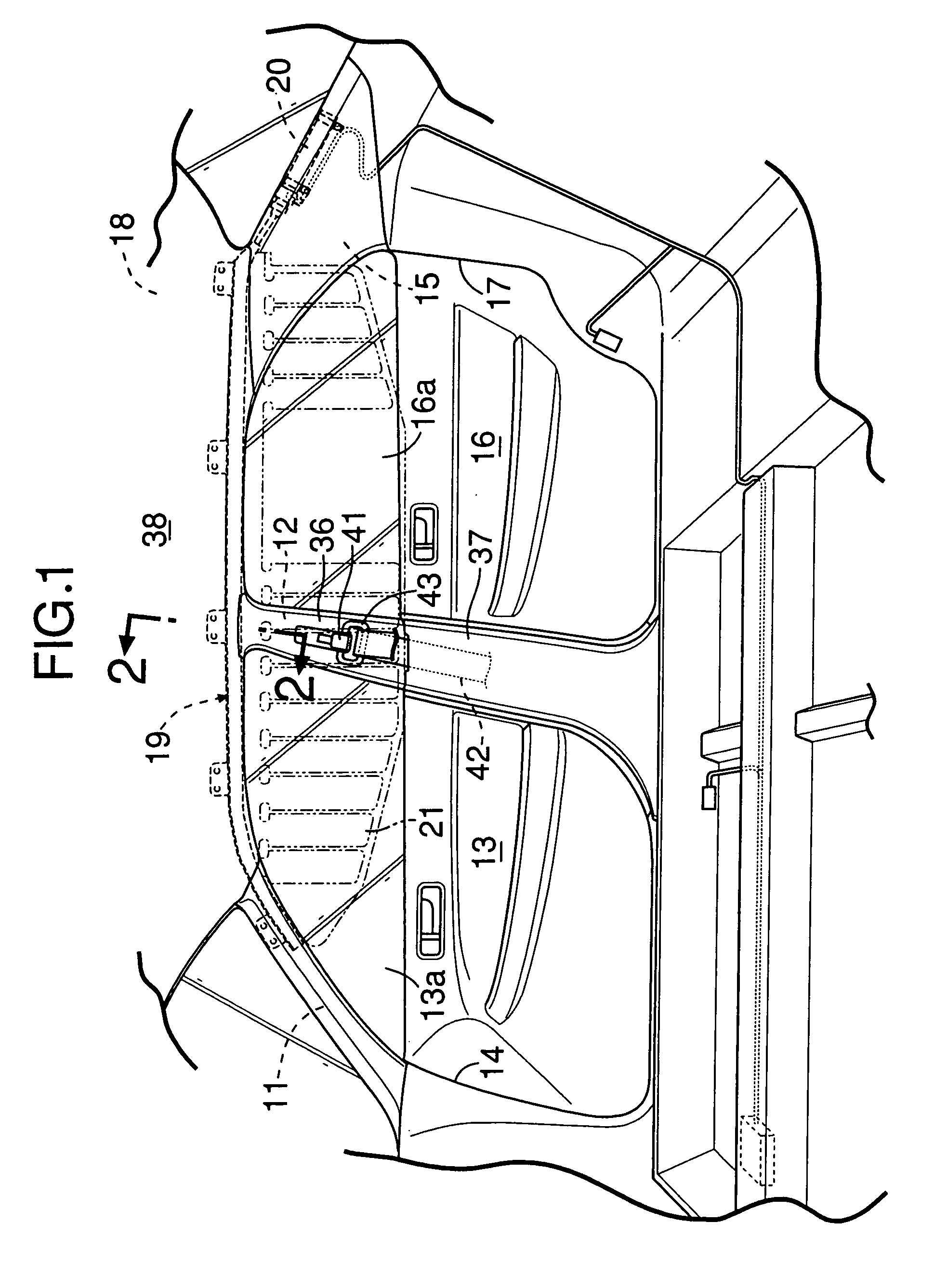
[0035]As shown in FIG. 1, on a side surface of a vehicle body of a vehicle, a door opening 14 in which a front door 13 is mounted is formed between a front pillar 11 and a center pillar 12, and a door opening 17 in which a rear door 16 is mounted is formed between the center pillar 12 and a rear pillar 15. An airbag module 19 is provided along a side edge of a roof 18 which extends from an upper end of the front pillar 11 to an upper end of the rear pillar 15. When acceleration of a predetermined value or higher is detected at a time of collision on the side surface of the vehicle or at a time of rolling over, an airbag 21 accommodated in the air bag module 19 is inflated by a high pressure gas which is supplied from an inflator 20 disposed inside the rear pillar 15, and deploys downward into a curtain shape from the side edge of the roof 18 so as to shield occupants seated on a front seat and a rear seat ...

second embodiment

[0048]Next, the present invention will be explained based on FIG. 5 and FIG. 6.

[0049]In this second embodiment, ribs 39m and 39m which project toward the first side wall 39 are provided at the second side wall 39e of the roof lining engaging groove 39g, which connects to a pair of airbag deployment guide walls 39h and 39h. Accordingly, when the end edge 38a of the roof lining 38 is engaged in the roof lining engaging groove 39g, the ribs 39m and 39m bite into the soft roof lining 38, and therefore, the roof lining 38 is made difficult to disengage from the roof lining engaging groove 39g to stabilize the assembly. In addition, the roof lining 38 is pressed against the first side wall 39d of the roof lining engaging groove 39g by the reaction force received from the ribs 39m and 39m, and therefore the gap in the connecting portion between the roof lining 38 and the upper pillar garnish 36 is made further smaller to thereby further improve the appearance.

third embodiment

[0050]Next, the present invention will be explained based on FIG. 7.

[0051]The third embodiment is a modification of the second embodiment, and the ribs 39m and 39m, which are provided at the second side wall 39e of the roof lining engaging groove 39g in the second embodiment, are extended to the bottom wall 39f of the roof lining engaging groove 39g in the third embodiment. In this situation, tolerance is set so that the position of the end edge 38a of the roof lining 38 at room temperature is located within a first predetermined distance D1 upward from upper ends of the ribs 39m and 39m on the bottom wall 39f, and is located outside a second predetermined distance D2 downward from the upper end of the first side wall 39d.

[0052]Accordingly, even when the temperature rises higher than the room temperature and the end edge 38a of the roof lining 38 is thermally expanded downward, the thermal expansion can be finally absorbed by the end edge 38a of the roof lining 38 biting into the r...


PUM


Abstract

An end edge of a roof lining is engaged in a roof lining engaging groove extending along a side surface of an upper end portion of a pillar garnish at a side of a pillar, thereby eliminating a gap in a connecting portion between the pillar garnish and the roof lining to improve the appearance. Airbag deployment guide walls extend to an outside of a vehicle compartment from an upper end of a roof lining engaging groove at the side of the pillar, and an airbag module is disposed at a position sandwiched by the pillar and the roof lining, above the airbag deployment guide walls. Therefore, an inflating airbag is guided to the side of the vehicle compartment so as not to be caught by the upper end of the pillar garnish and can be deployed into the vehicle compartment by reliably pressing to open the roof lining, without providing a special guide member.

Description

BACKGROUND OF THE INVENTION[0001]1. Field of the Invention[0002]The present invention relates to an occupant restraint system in which an airbag module accommodating an airbag in a folded state is placed along a side edge of a roof, and the airbag inflated at a time of collision of a vehicle presses to open a connecting portion between a roof lining covering the roof from a side of a vehicle compartment and a pillar garnish covering a pillar from the side of the vehicle compartment, and deploys downward into the vehicle compartment.[0003]2. Description of the Related Art[0004]Japanese Patent Application Laid-open No. 2001-122073 discloses an occupant restraint system in which a horizontal guide wall 32f extending to a center pillar 22, and a projection 32a extending upward from a tip end of the guide wall 32f and engaging in a mounting hole 22b of the center pillar 22 are provided at an upper part of a center pillar garnish 32, and a gap between the center pillar 22 and the center p...

Claims


Application Information

Patent Timeline
Patent Type & Authority Patents(United States)
IPC IPC(8): B60R21/16B60R13/02B60R11/02B60R21/20B60R21/213B60R22/20
CPCB60R21/213B60R13/0225B60R13/025B60R22/201B60R2021/161B60R2011/0288B60R2013/0287B60R2013/0293B60R2011/0276
Inventor HIROSE, TOSHIKAZU
Owner HONDA MOTOR CO LTD
Why Eureka
Try Eureka