
Electronic device with UV illumination arrangement

a technology of electronic devices and illumination arrangements, applied in the direction of measurement devices, thermometer details, instruments, etc., can solve the problems of consuming a large amount of energy, unable to describe or suggest the most efficient downward direction of light, and the idea of less than desirable, etc., to achieve the effect of improving illumination

Inactive Publication Date: 2007-02-06
TIMEX GROUP
View PDF8 Cites 13 Cited by
  • Summary
  • Abstract
  • Description
  • Claims
  • Application Information

AI Technical Summary

Benefits of technology

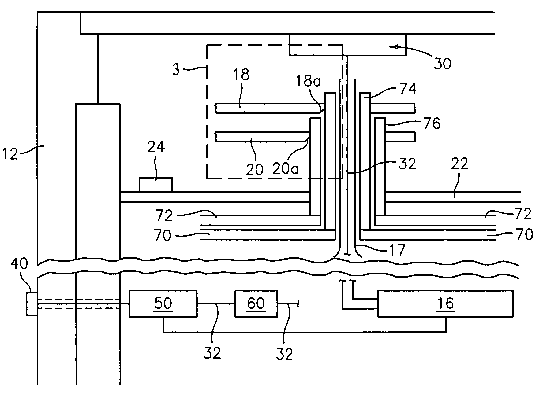
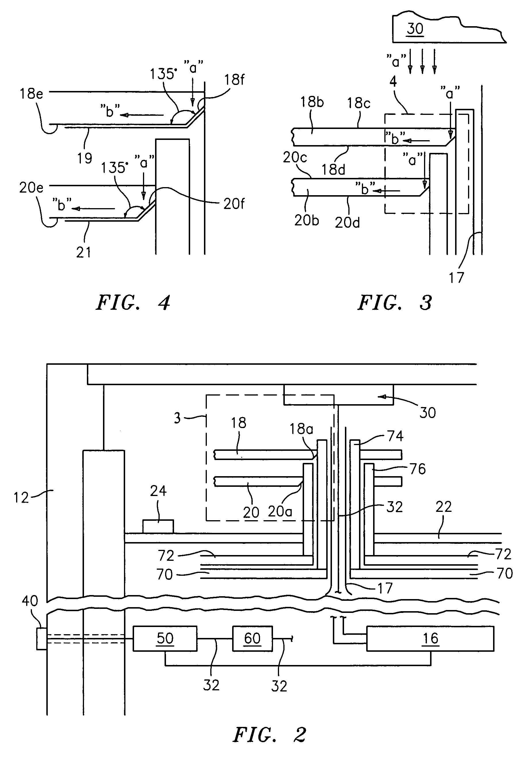
[0008]Specifically, it is an objective of the present invention to provide an improved illumination arrangement for an electronic device that provides for improved illumination of one or more indicator hands using UV lightwaves.

Problems solved by technology

However, both of these ideas are believed to be less than desirable due to their inability of most efficiently directing the light into the hands of the device.
Although the idea of providing a lightsource above the dial (as opposed to below or on the side) is known from U.S. Pat. No. 6,299,321, this patent also lacks any description or suggestion of most efficiently directing the light downwardly into the hands, as it too describes the mere idea of “blasting” light towards the hands.
There is also a need to overcome the perceived deficiencies in merely using an LED that emits light in the visible spectrum, as such devices do not provide for a satisfactory illumination of the hands, and they also use a considerable amount of energy, relatively speaking.

Method used


Image

  • Electronic device with UV illumination arrangement
  • Electronic device with UV illumination arrangement
  • Electronic device with UV illumination arrangement

Examples


Embodiment Construction

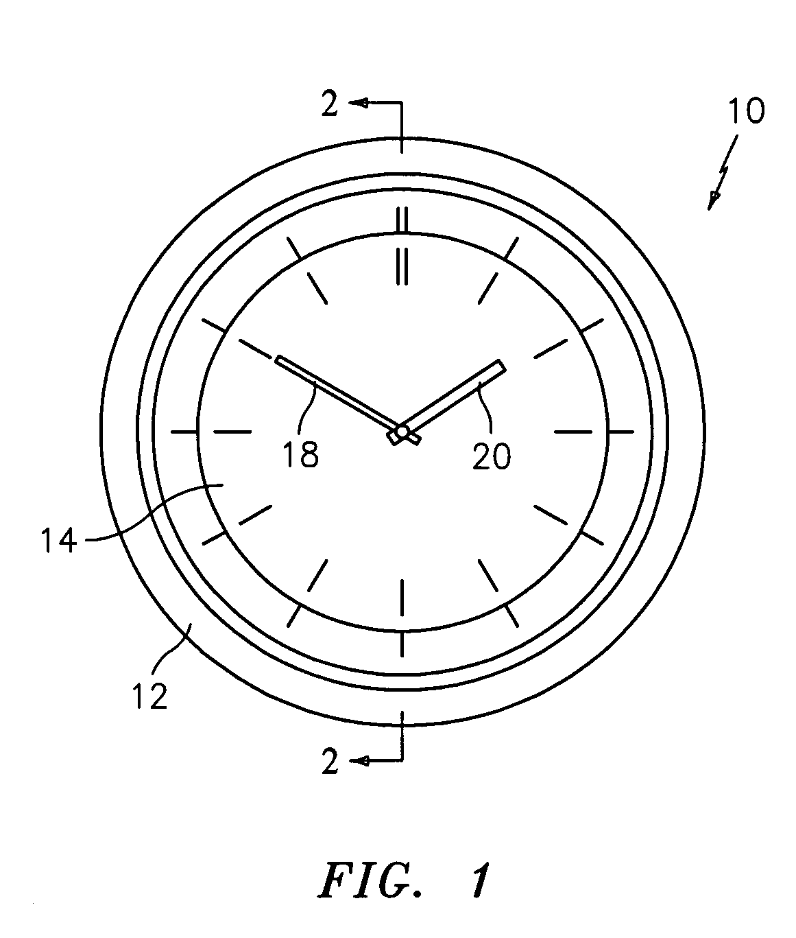
[0020]The present invention is directed to an illumination arrangement for an electronic device, which in the preferred embodiment, is a wristwatch. However, it should be understood that the present invention need not be a wristwatch, as other devices are very much contemplated hereby, and thus covered by the present claims. Reference should be made to co-owned and co-pending application Ser. No. 10 / 441,417, the disclosure of which is incorporated by reference as if fully set forth herein, which makes it clear that the device of the present invention can be a heartrate monitor and / or a compass, just to name a few.

[0021]Turning to the preferred embodiment, the Figures illustrate an electronic device, generally indicated at 10, constructed in accordance with the present invention. Device 10, which in the preferred embodiment is a wristwatch, comprises a watch case 12, a watch crystal 14, and an actuation mechanism, generally indicated at 16 and which in the preferred embodiment is a s...


PUM


Abstract

An indicator hand illumination arrangement for use in an electronic device that comprises a casing, a dial positioned in the casing, at least one indicator hand positioned intermediate the dial and a cover for at least in part protecting the at least one indicator hand and the dial, wherein the arrangement comprises a light emitting element coupled to the cover, for emitting lightwaves in the UV spectrum towards the at least one indicator hand and in a direction perpendicularly to the dial surface; wherein the at least one indicator hand has a proximate end that is coupled to a stem and a distal end, the at least one indicator hand having a top surface, an inner and outer bottom surface, and a angled surface angled non-perpendicularly to the angle of the lightwaves; such that lightwaves that emanate from the light emitting element deflect off of the angled surface and propagate in a direction towards the distal end of the at least one indicator hand.

Description

BACKGROUND OF THE INVENTION[0001]The present invention is directed generally to illumination arrangements in electronic devices, such as wristwatches (by example and not by limitation), and, in particular, to an improved illumination arrangement for illuminating elements in the device, such as one or more indicator hands, such as the hour and minute hand, by way of example.[0002]The technology for illuminating the hands of an electronic device is quite varied. Some of the more readily accessible designs can be found in U.S. Pat. No. 3,490,226 (clock); U.S. Pat. No. 5,546,888 (gauges); U.S. Pat. Nos. 5,697,322; 5,751,622 and Published application No. 2003 / 0112712. Most of these technologies illuminate the hands from the bottom (i.e. from the dial side of the device).[0003]The use of ultraviolet light to illuminate the hands of a timepiece is also known. For example, U.S. Pat. No. 4,561,042 and Published application No. WO 2004 / 034153 describe the use of a light emitting element mount...

Claims


Application Information

Patent Timeline
IPC IPC(8): G01D11/28
CPCG01D11/28
Inventor DITTUS, DOMINIK
Owner TIMEX GROUP
Learn More