Solid state electric light bulb

a technology of electric light bulbs and solid state replacement, which is applied in the direction of electric discharge lamps, electrical device connections, lighting and heating apparatus, etc. it can solve the problems of increasing the cost of electric illumination to the consumer, the acrylic or plastic globe version of these unique solid state lighting units is not easily physically damaged, and the effect of increasing safety

a technology of electric light bulbs and solid state replacement, which is applied in the direction of electric discharge lamps, electrical device connections, lighting and heating apparatus, etc. it can solve the problems of increasing the cost of electric illumination to the consumer, the acrylic or plastic globe version of these unique solid state lighting units is not easily physically damaged, and the effect of increasing safety

US7172314B2Inactive Publication Date: 2007-02-06PLASTICS INVENTIONS & PATENTS INC

Image

  • Solid state electric light bulb
  • Solid state electric light bulb

Examples


Embodiment Construction

(s)

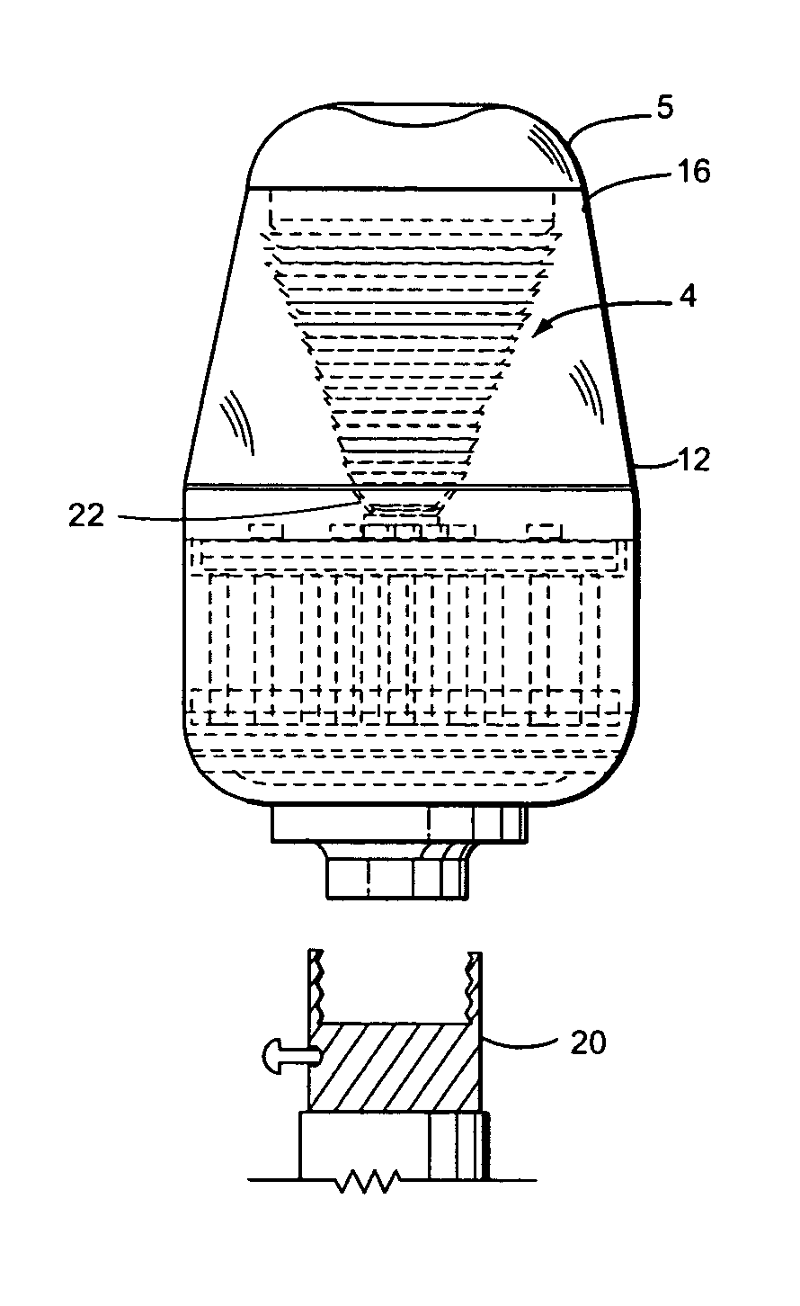
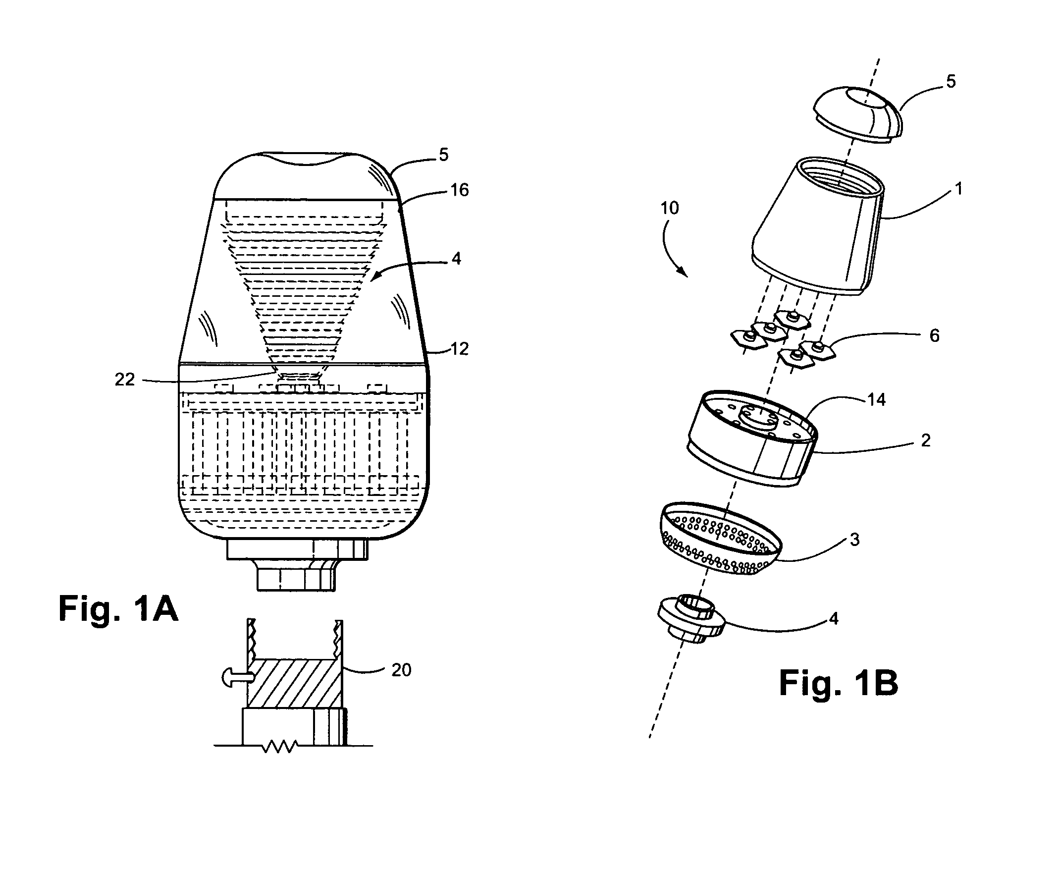
[0022]The present invention is to a solid-state light bulb which replaces a current electric light bulb. As best shown by reference to the figures, the invention will be disclosed in further detail.

[0023]According to the present invention, a solid state light bulb 10 includes a bulb socket 4 is connected to a heat sink base mount 3. The bulb socket 4 preferably is sized and arranged to electrically mate with a lamp socket 20 when the bulb socket 4 is threadedly or otherwise attached to the lamp socket. The lamp socket 20 is preferably a “household lamp socket” which is hereby defined as a conventional lamp socket configured to accept a standard 60 Watt, 120 V light bulb available from Phillips or General Electric.

[0024]The heat sink unit 2 includes an integrated AC to DC power supply which is machined to fit snugly into heat sink base mount 3. LEDs 6 may be soldered to DC voltage connections on the upper side of heat sink unit 2. An optically conductive acrylic bulb globe 1 fits ...


PUM


Abstract

A solid state light bulb for attachment to a lamp socket. The light bulb uses a number of super bright LEDs or color LEDs mounted within a hollow housing to replace a standard bulb such as a 60 Watt bulb. A stepped, reverse conical interior wall distributes and diffuses the light to project the appearance of a normal bulb. An upper lens of the housing may be removable to form a spot light effect.

Description

CROSS REFERENCE TO RELATED APPLICATIONS[0001]This application claims the benefit of U.S. Provisional Application 60 / 490,445 filed Jul. 29, 2003, which is hereby incorporated by reference. This application also claims the benefit of U.S. Provisional Application 60 / 490,441 filed Jul. 29, 2003, which is hereby incorporated by reference.BACKGROUND OF THE INVENTION[0002]A. Field of the Invention[0003]The present invention relates to a solid state replacement for an electric light bulb.[0004]B. Description of the Prior Art[0005]At the present time conventional American electric light bulbs utilize 115 VAC to generate sufficient electric current through a filament mostly of tungsten to heat the filament until light and heat are emitted. The light from the filament is dispersed through the glass globe in all directions except through the socket. Most economically produced bulbs of this configuration have a finite use life. Bulbs of this type can and are made to last longer than the more eco...

Claims


Application Information

Patent Timeline
06 Feb 2007
Publication
US7172314B2
IPC
F21V11/00; F21K99/00; H01R33/94; H01R33/945
CPC
H01R33/94; F21K9/13; F21Y2101/02; Y10S362/80; H01R33/9453; F21K9/23; F21Y2115/10
Inventors
CURRIE, ROBERT M.; SORELLA, ELIOT