
Electric energy supply system for a ship, in particular a navy ship that can be operated with low IR signature

a technology for electric energy supply systems and ships, applied in the direction of electrochemical generators, marine propulsion, vessel construction, etc., can solve the problems of inability to detect exhaust gases and ship propulsion, and achieve the effect of reducing power consumption, avoiding reliability, and improving the reliability of the starting process of the propulsion system which is required to reach high speeds

Inactive Publication Date: 2007-02-06
SIEMENS AG
View PDF10 Cites 9 Cited by
  • Summary
  • Abstract
  • Description
  • Claims
  • Application Information

AI Technical Summary

Benefits of technology

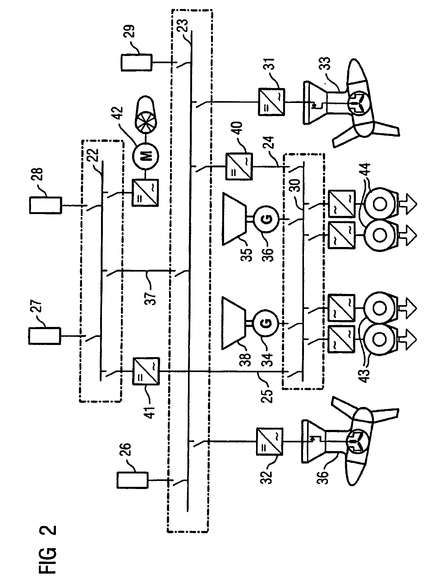
[0005]The particular requirements for a power supply system for an AES are taken into account in particular in that the AC and DC power supply systems are connected to one another such that electrical power can be interchanged between them, and in that electrical power is drawn from the DC power supply system and transferred to the AC power supply system in particular for starting the engine drives. It is thus advantageously possible to achieve a starting process with a low IR signature for high-speed propulsion systems.
[0019]A refinement of an embodiment of the invention in this case provides for the AC and DC switching systems to be designed such that, when there is a high demand for power in the DC power supply system, for example when using high-energy weapons, it is possible to feed a maximum amount of power from the AC power supply system to the DC power supply system. Furthermore, in this context, provision is also made for the DC power supply system to have high-dynamic response energy stores, for example rechargeable battery banks or flywheel energy stores. These devices have the common feature that their operation can be used to cope with sudden demands for power to be made available in the ship power supply system. The AC and DC power supply systems are thus designed such that electrical power can be used from both power supply systems in order to meet the requirement.

Problems solved by technology

Thus, since the exhaust gas bubbles which are formed do not rise until behind the stern of the ship where they merge into the stern vortices, this actually results in the ship being propelled in a manner in which the exhaust gases cannot be detected.

Method used


Image

  • Electric energy supply system for a ship, in particular a navy ship that can be operated with low IR signature
  • Electric energy supply system for a ship, in particular a navy ship that can be operated with low IR signature
  • Electric energy supply system for a ship, in particular a navy ship that can be operated with low IR signature

Examples


Embodiment Construction

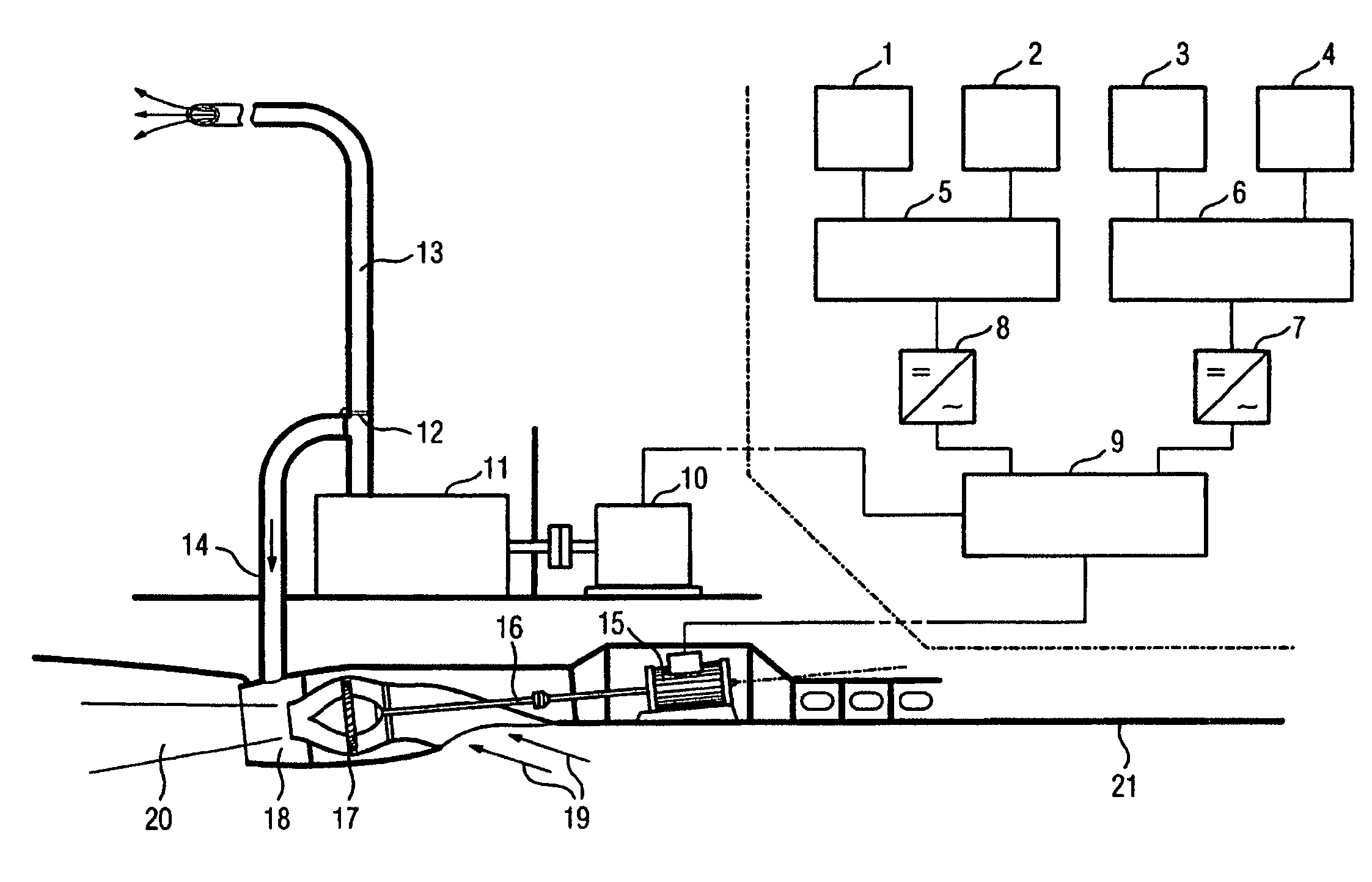
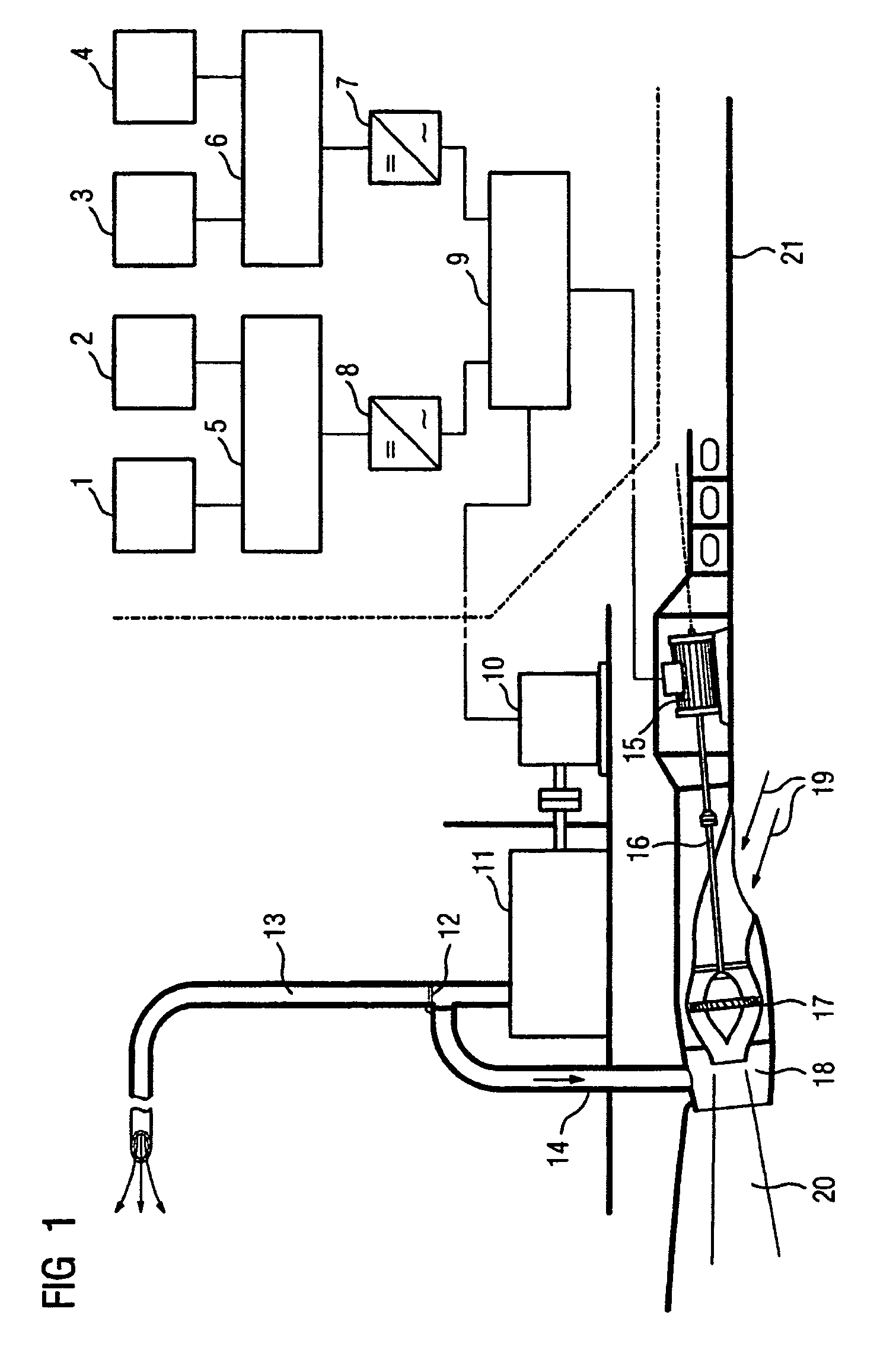
[0031]In FIGS. 1, 1, 2, 3 and 4 each denote a fuel cell unit which may optionally comprise a PEM cell block or a combination of a PEM cell block with another fuel cell with a higher operating temperature. A functional combination of the two different fuel cells is produced in a combination such as this. The electrical power which is produced by the fuel cell systems 1, 2, 3 and 4 is passed to electrical DC switching systems 5, 6 which, if required, may also be combined, and in which case more than two DC switching systems (electrical mechanisms) may also be arranged depending on the safety, reliability and redundancy requirements, and passed from here via DC / AC converters 7, 8 to the electrical switching system 9, an AC switching system.

[0032]Both the generator 10 and the electric motor 15 for the water jet 17 are switched by the electrical switching system 9. The generator 10 is connected to the gas turbine 11, whose exhaust gases are optionally passed to the atmosphere—switchably ...


PUM


Abstract

The invention relates to an electric energy supply system for a ship, in particular for a navy ship that can be operated with a low IR signature and that is configured as an <<all electric ship>> (AES). Said system comprises a direct current network (DC), supplied by fuel cells, as a ship electrical system and network for normal propulsion and an alternating current network (AC) comprising generators, in particular for generating energy for high-speed propulsion. According to the invention, the generators are motor-driven, e.g. by means of at least one gas turbine or one diesel motor, preferably supercharged and the AC and DC network are interconnected in such a way that electric energy can be exchanged between them, in particular that electric energy can be withdrawn from the DC network and transferred to the AC network to start the motor-driven propulsion.

Description

[0001]This application is the national phase under 35 U.S.C. § 371 of PCT International Application No. PCT / DE2003 / 002152 which has an International filing date of Jun. 27, 2003, which designated the United States of America and which claims priority on German Patent Application number DE 10231152.8 filed Jul. 10, 2002, the entire contents of which is hereby incorporated herein by reference.FIELD OF THE INVENTION[0002]The invention generally relates to an electrical power supply system for a ship. In particular, it relates to one for a navy ship which can be operated with a low IR signature, which is in the form of an “All Electric Ship” (AES) having a DC power supply (DC), which is fed from fuel cells, as the ship power supply system and as a power supply system for normal speed propulsion systems. The system further preferably includes an AC power supply system (AC) with generators, in particular for power generation for high-speed propulsion systems. The generators are preferably...

Claims


Application Information

Patent Timeline
Patent Type & Authority Patents(United States)
IPC IPC(8): B60L11/02B60L50/10B63G13/02B63H21/32B63H23/24
CPCB63G13/02B63H21/32B63H23/24Y02T90/40B63H21/17
Inventor RZADKI, WOLFGANGSADLER, KARL-OTTOSCHULZE HORN, HANNES
Owner SIEMENS AG
Learn More