Drill sharpener

a drill bit and sharpener technology, applied in the direction of wrench drills, manufacturing tools, other manufacturing equipment/tools, etc., can solve the problem of generating a large amount of debris

Inactive Publication Date: 2007-02-06
DAREX
View PDF20 Cites 14 Cited by
  • Summary
  • Abstract
  • Description
  • Claims
  • Application Information

AI Technical Summary

Benefits of technology

[0011]A debris collection tube has been developed which can be inserted into the point-splitting port to substantially prevent debris from exiting the unit. The tube is provided with a cap which will serve as a physical barrier to the debris, and is vented to allow airflow therethrough. The cap is also removable if it is desired to attach the collection tube to a vacuum unit.

Problems solved by technology

A considerable amount of debris is generated when the drill is being sharpened, particularly in the sharpening of the cutting surfaces.

Method used


Image

  • Drill sharpener
  • Drill sharpener
  • Drill sharpener

Examples


Embodiment Construction

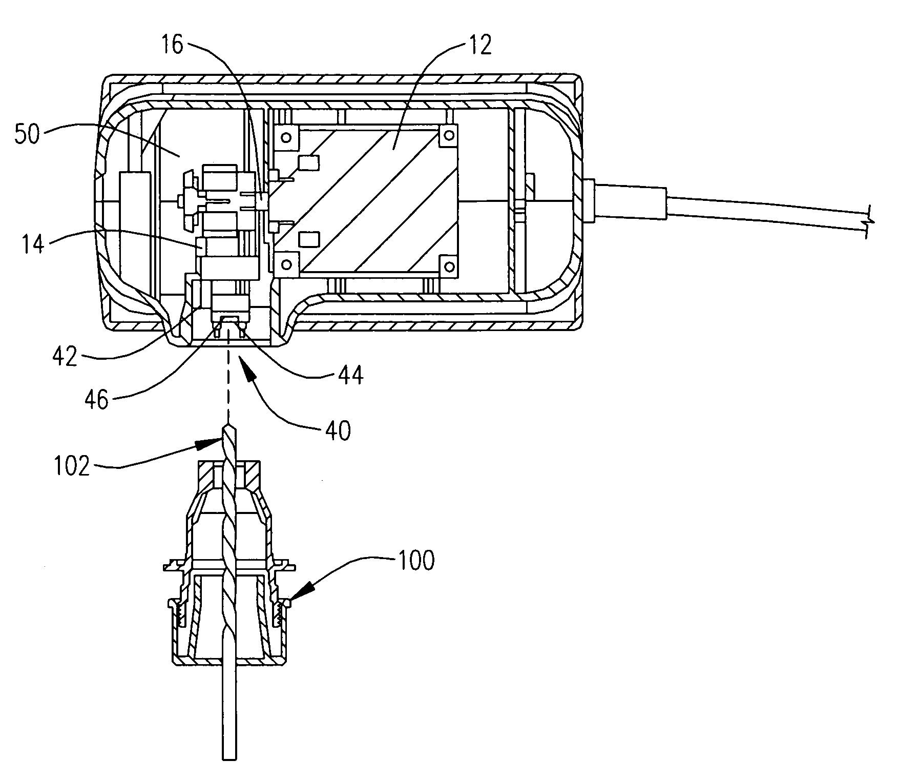
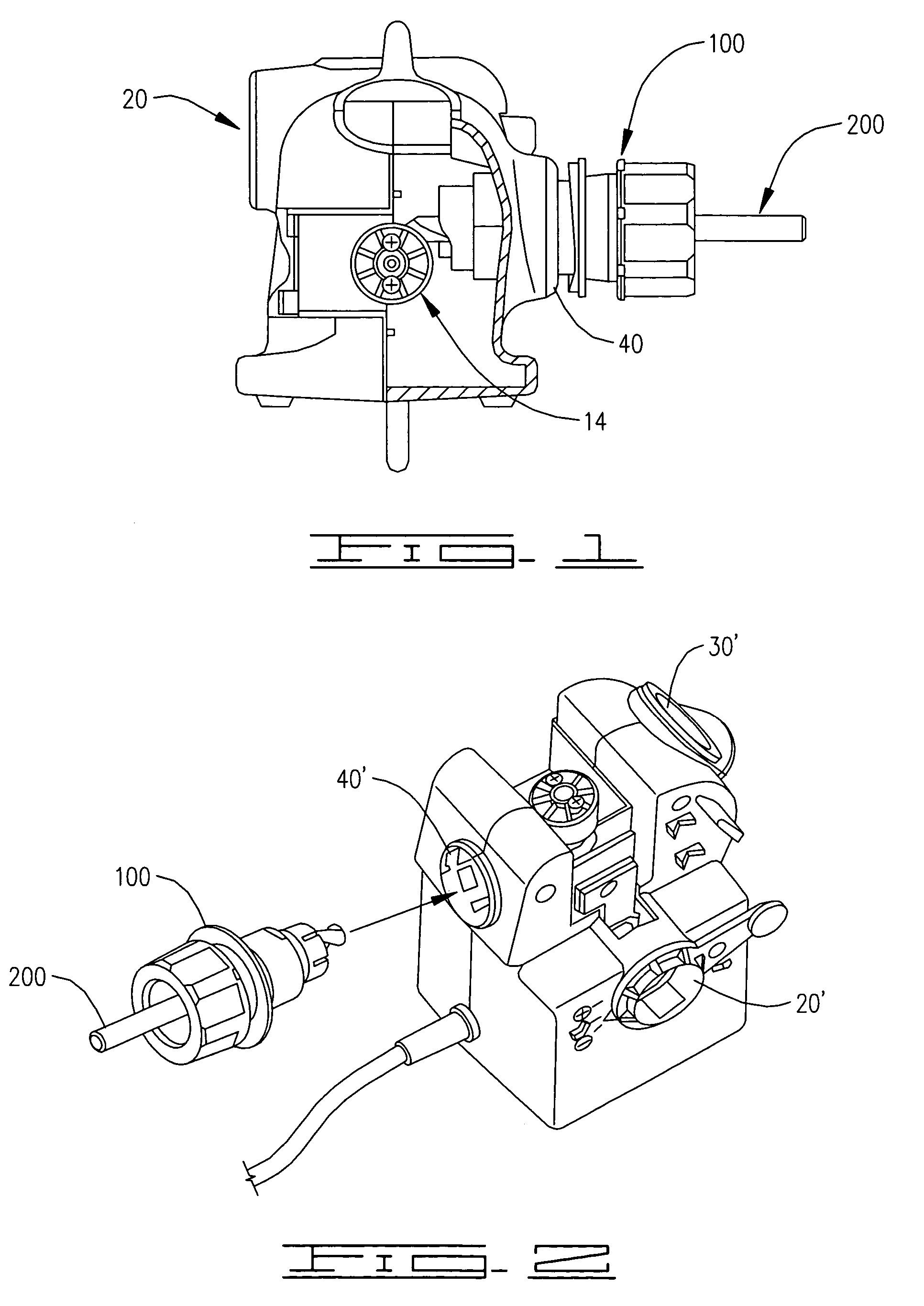
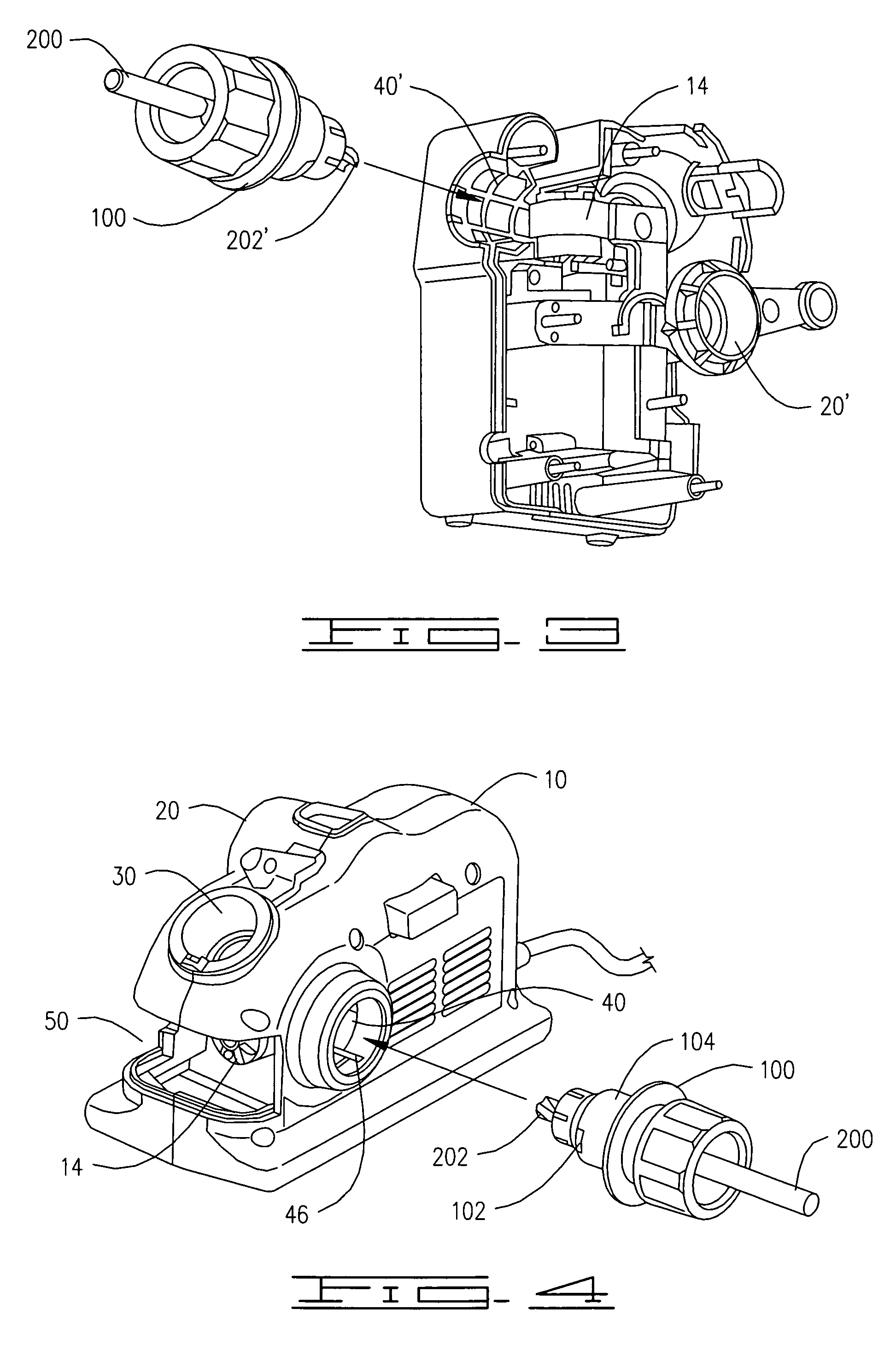
[0020]The drill sharpener according to a preferred embodiment of the present invention includes a housing 10, which encloses a motor 12 and a grinding wheel assembly 14. The motor is preferably a high-speed motor capable of operating at speeds on the order of about 15,000–20,000 RPM. The grinding wheel assembly is preferably substantially identical to that disclosed in the '732 patent, and the diameter of the diamond-plated ring that forms the grinding surface is preferably on the order of ½ to 2½ inches. Even more preferably, the diameter of the ring is about 1 to 1½ inches. Further, a diameter of 1¼ inches is preferred.

[0021]The grinding wheel assembly 14 is operably coupled to the shaft 16 of the motor, preferably in a direct drive engagement. It can be seen in the several drawing figures that the unit may take on a vertical orientation, with the motor shaft extending vertically upwardly with the grinding wheel assembly positioned above, in the manner disclosed in the '732 patent...


PUM

PropertyMeasurementUnit
diameteraaaaaaaaaa
resilientaaaaaaaaaa
lengthaaaaaaaaaa

Abstract

A drill sharpener is provided which has a point-splitting port which simplifies the procedure for producing a split point on a drill bit undergoing sharpening. The point-splitting port is positioned relative to a grinding wheel assembly such that, when the drill held by a chuck is advanced toward the grinding wheel, a flute of the drill at the drill tip is brought into contact with the grinding wheel. The port has alignment stops therein which mate with flats provided on the barrel of the chuck to ensure proper alignment of the chuck and drill relative to the grinding wheel. The stops also limit the extent of inward travel of the chuck and drill to a predetermined distance. A debris or grit collection tube is also provided to be inserted into an unused port of the drill sharpener, to contain and confine any debris or grit attempting to exit the sharpener through the unused port.

Description

CROSS-REFERENCE TO RELATED APPLICATION[0001]This application relates to, and claims the benefit of the filing date, of U.S. Provisional Application Ser. No. 60 / 413,772, filed Sep. 27, 2002.BACKGROUND OF THE INVENTION[0002]1. Field of the Invention[0003]The present invention relates to a power drill sharpener, and more specifically to a power drill sharpener having a push-in point splitting port and a tube designed to collect debris generated in a drill sharpening process.[0004]2. Description of Related Art[0005]Drill sharpeners are known for use in industrial environments. In high-volume manufacturing operations, high-quality, precision drill sharpeners, even though quite expensive to purchase, are recognized as being cost effective devices. The use of a drill sharpener will prolong the effective life of a drill, thereby reducing costs by reducing consumption of the drill bits, and using sharp drill bits improves production quality and yield of products requiring bores or holes to b...

Claims


Application Information

Patent Timeline
Patent Type & Authority Patents(United States)
IPC IPC(8): B24B7/00B24B19/00B24B55/04B24B9/00B24B3/24B24B3/26
CPCB24B3/24B24B3/265B24B3/26B24B3/247
Inventor BERNARD, DAVID A.CHRISTIAN, WILLIAM C.HARRIS, SCOTTMOSTTLER, KEITH
Owner DAREX
Why Eureka
Try Eureka