Transmit power control for mobile unit

a technology of power control and mobile unit, applied in power management, data switching by path configuration, electrical equipment, etc., can solve the problems of increasing rf interference between access points, reducing the power output of mobile units,

Inactive Publication Date: 2007-02-06
SYMBOL TECH LLC
View PDF3 Cites 14 Cited by
  • Summary
  • Abstract
  • Description
  • Claims
  • Application Information

AI Technical Summary

Problems solved by technology

As the distance between access points is reduced, RF interference between access points can increase.
It is difficult, however, to generally reduce the power output of mobile units, because the mobile unit may sometimes be used in an area where there is a high density of access points, and accordingly, only a lower transmittal power is required, and also the same mobile units may roam into an area in which access points are spaced at further distances, and the full power of the mobile unit is required to effectively transmit to the access points.

Method used


Image

  • Transmit power control for mobile unit
  • Transmit power control for mobile unit
  • Transmit power control for mobile unit

Examples


Embodiment Construction

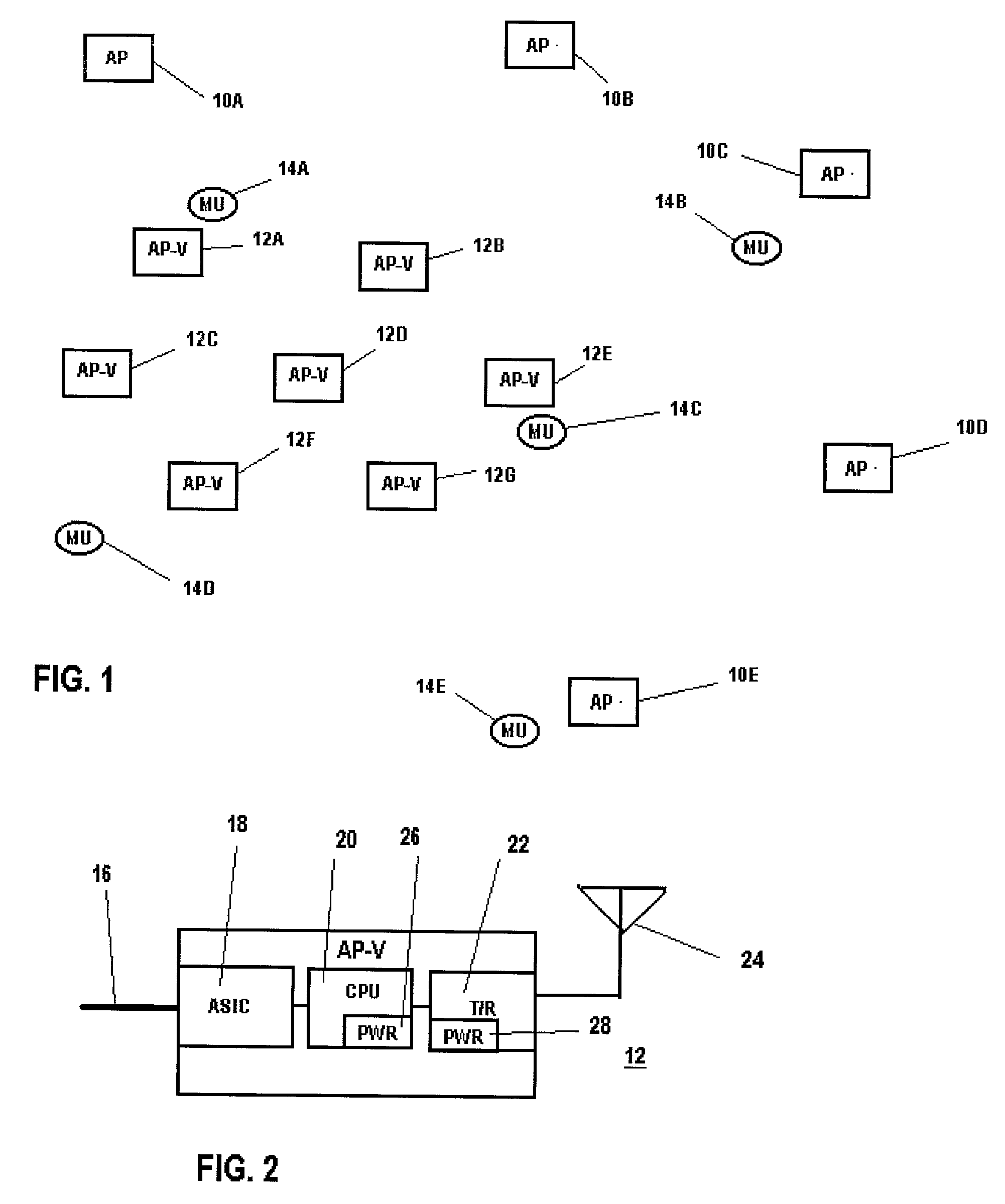
[0015]Referring to FIG. 1, there is shown a map illustrating exemplary locations of fixed power access points 10A through 10E, variable power access points 12A through 12G and mobile units 14A through 14E in a wireless local area network. In the network illustrated in FIG. 1, access points 10A through 10E may have fixed transmitter power and are arranged at a wider spacing between adjacent access points, which is selected according to the transmitter power, and hence the range of each access point 10. Variable power access points 12A through 12G are provided in a central area, wherein a greater volume of data traffic may be anticipated. For example, variable power access points 12A through 12G may be provided for servicing mobile units within a central laboratory area of an industrial complex, wherein a high volume of data transmission might be anticipated, while access points 10A through 10E may be provided in peripheral areas, wherein a smaller number of mobile units, and hence a ...


PUM


Abstract

In a wireless local area network which includes access point having variable transmitter power levels, transmitter power data is sent from the access points to the mobile units and used by the mobile units in order to provide a corresponding variation in the transmitter power of the mobile unit.

Description

BACKGROUND OF THE INVENTION[0001]This invention relates to wireless local area networks (WLAN) and particularly, to avoidance of radio interference in such networks. As data rates of WLAN systems increase, more access points are required and the effective range of a higher data rate signals between the access point and mobile units is reduced. In order to provide sufficient high bandwidth connectivity for mobile units, the density of access point population is increased, particularly, in areas in which a high number of mobile units are anticipated. The close distribution of access points is sometimes referred to as micro-cell distribution. As the distance between access points is reduced, RF interference between access points can increase. One technique for controlling such interference is reduce the transmit power output of the access points, to thereby reduce their range and reduce interference.[0002]Interference can also exist between transmissions of mobile units. It is difficul...

Claims


Application Information

Patent Timeline
Patent Type & Authority Patents(United States)
IPC IPC(8): H04B1/00H04B7/005H04L12/28H04W52/08
CPCH04W52/08
Inventor KLEIN, JOHNMONTGOMERY, RICHARDNGUYEN, DONGWERBACK, ANDREWKELLOGG, WILLIAMOUCHIDA, WAYNEMELVILLE, GRAHAM
Owner SYMBOL TECH LLC
Why Eureka
Try Eureka