Method and system for identifying the degree of a slip of a belt part of a belt transmission

a belt transmission and belt part technology, applied in the direction of instruments, mechanical equipment, gearing, etc., can solve the problems of transmission damage, transmission damage, and transmission damage, and achieve the effect of reducing the number of belt parts

Inactive Publication Date: 2007-02-06
ROBERT BOSCH GMBH
View PDF9 Cites 12 Cited by
  • Summary
  • Abstract
  • Description
  • Claims
  • Application Information

AI Technical Summary

Benefits of technology

[0026]The system according to class for detecting a slip of the belt part builds upon the state of the art according to the class in that the system detects a slip of the belt part via the evaluation of the change of the transmission rpm ratio. The transmission rpm ratio can be determined, similarly to the method of the invention, via a quotient of the primary rpm (for example, a drive conical wheel pair) and a secondary rpm (for example, the rpm of an output conical wheel pair). As mentioned, the primary rpm and the secondary rpm in standard belt transmissions are anyway detected so that no additional hardware complexity is required with respect thereto. Also with the system of the invention, countermeasures can be initiated, for example, already with the first detection of a slip before a destruction of the belt part occurs, for example, of a thrust member band, or increased wear occurs.
[0031]Especially in the presently explained connection, it can be provided in the system of the invention that the belt part runs over the conical wheel pairs at an adjustable contact pressure and that the system adjusts the contact pressure in dependence upon the state of wear of the belt part in a manner similar as in the method of the invention. With the system of the invention, the contact pressure is also preferably increased by degree in order to not unnecessarily increase the losses of the transmission.

Problems solved by technology

In belt transmissions, it is problematic when the belt part, which transmits torques between two rotating elements, has slippage, that is, the belt part moves without grasping.
In this case, considerable damage can occur to the belt transmission, especially, considerable wear of the belt part can occur.
At times, the transmission can be destroyed when a slippage of the belt part occurs which is too great.
By increasing the contact pressure, a slippage of the belt part can, as a rule, be avoided; however, an increased contact pressure leads to an unwanted increase of the losses, for example, pump losses.

Method used


Image

  • Method and system for identifying the degree of a slip of a belt part of a belt transmission
  • Method and system for identifying the degree of a slip of a belt part of a belt transmission
  • Method and system for identifying the degree of a slip of a belt part of a belt transmission

Examples


Embodiment Construction

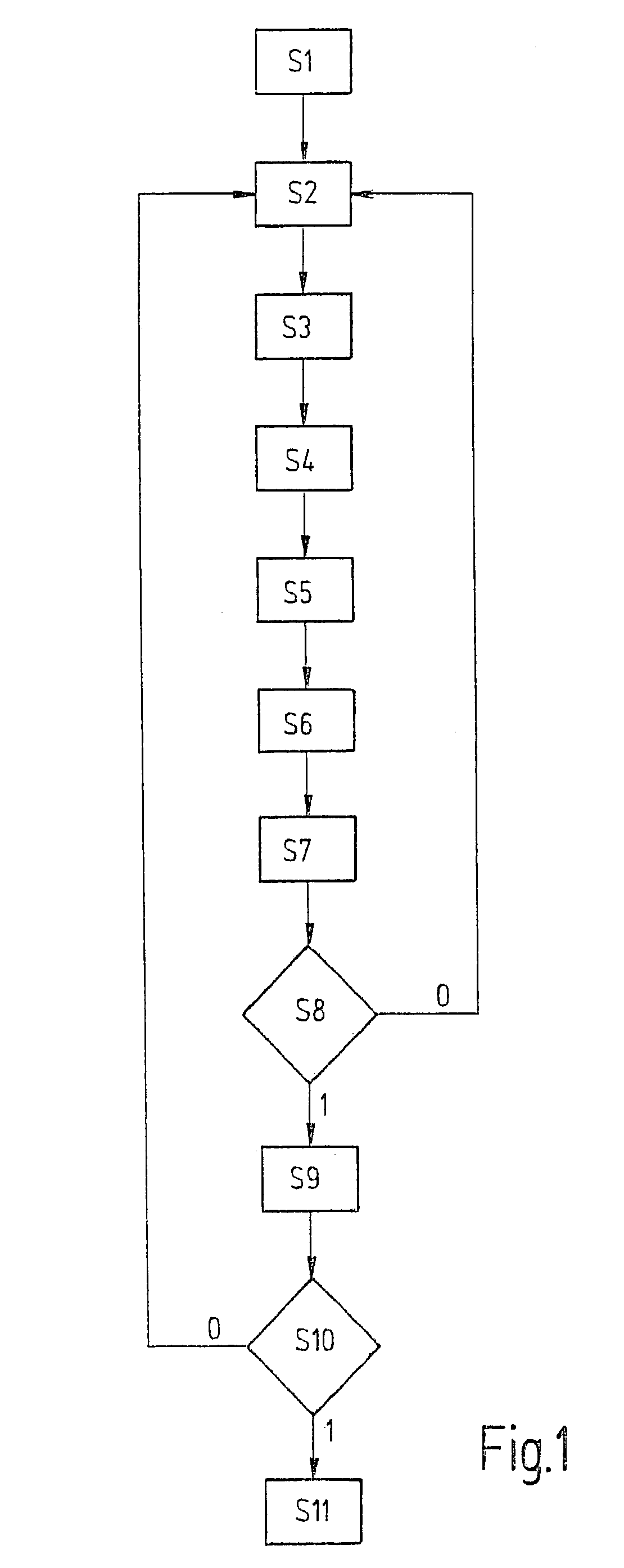
[0052]FIG. 1 shows a flow diagram which explains the execution of an embodiment of the method of the invention. The significance of the steps S1 to S11, which are shown in FIG. 1, will be evident from the following table.

[0053]

StepExplanationS1StartS2detect primary rpm (npm)S3detect secondary rpm (nse)S4compute transmission rpm ratio (ji)S5determine compensation term (K)S6determine normalization term (N)S7determine slip change ds (n)S8slip change ds (n) ≧ threshold value SW?S9initiate countermeasuresS10End?S11End

[0054]The embodiment of the method of the invention shown in FIG. 1 starts with step S1.

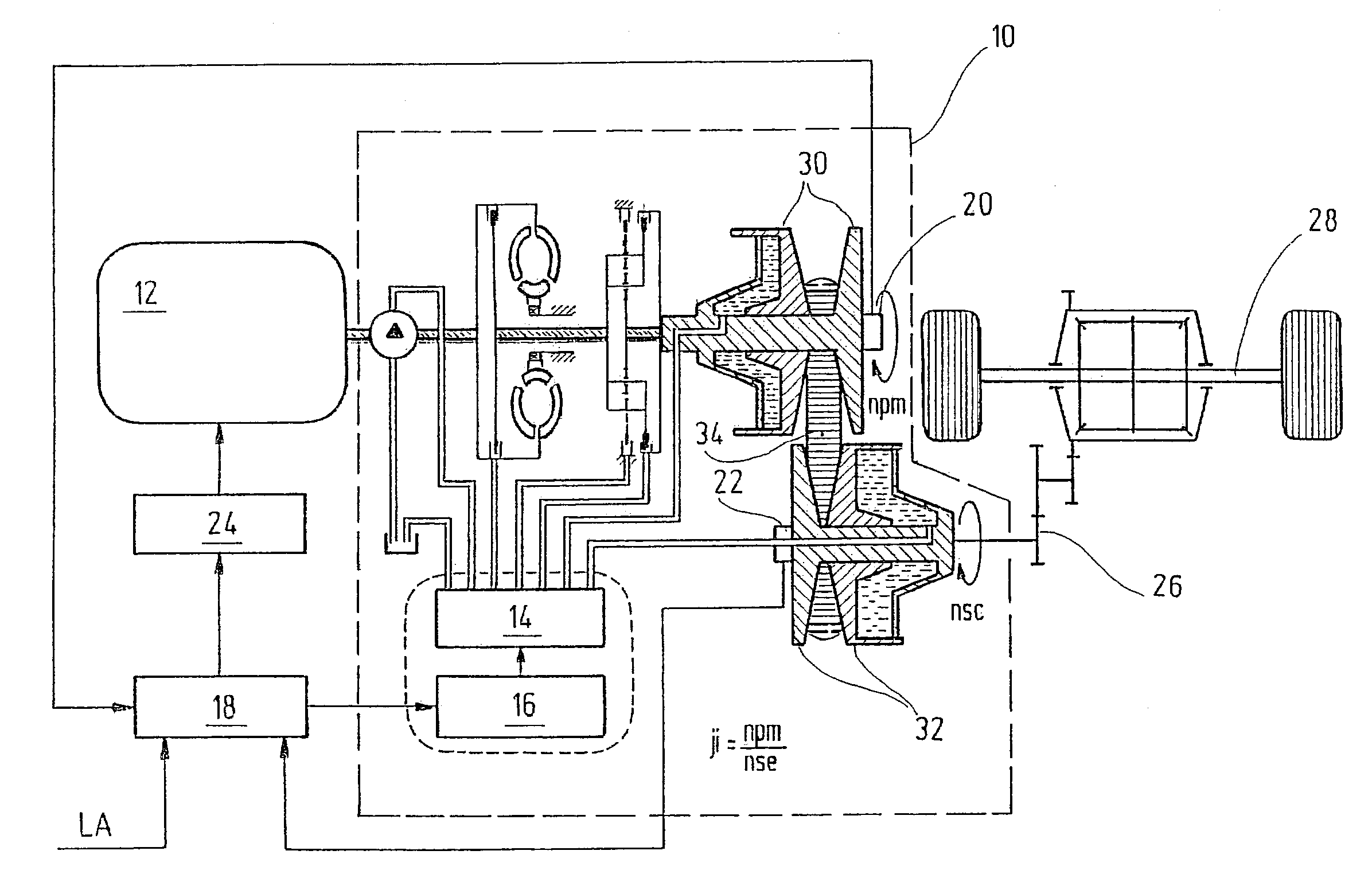
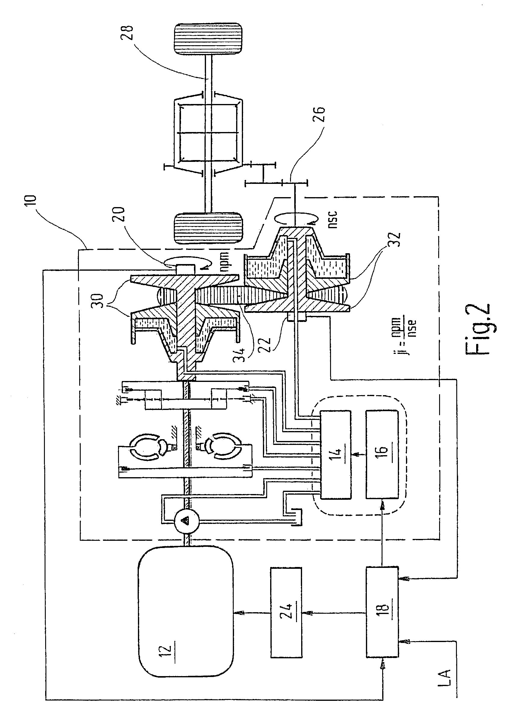
[0055]In step S2, the primary rpm npm is detected. For this purpose, the rpm sensor, which is identified in FIG. 2 by 20, can, for example, be used. The sensor supplies a signal for the rpm of a drive or primary conical wheel pair 30.

[0056]At step S3, the secondary rpm nse is detected. For this purpose, the rpm sensor, which is identified in FIG. 2 with 22, can, for example, be used. This...


PUM


Abstract

The present invention relates to a method for detecting a slip (s) of a belt part of a belt transmission, especially of a CVT transmission, having a transmission rpm ratio (ji).According to the invention, a slip of the belt part is detected by evaluating the change of the transmission rpm ratio (ji).

Description

[0001]This application is the national state of PCT / DE02 / 01954, filed on May 28, 2002. designating the U.S.FIELD OF THE INVENTION[0002]The invention relates to a method for detecting a slip of a belt part of a belt transmission, especially of a CVT transmission. The belt transmission has a transmission rpm ratio.[0003]The invention relates further to a system for detecting a slip of a belt part of a belt transmission, especially of a CVT transmission, having a transmission rpm ratio.BACKGROUND OF THE INVENTION[0004]In belt transmissions, it is problematic when the belt part, which transmits torques between two rotating elements, has slippage, that is, the belt part moves without grasping. In this case, considerable damage can occur to the belt transmission, especially, considerable wear of the belt part can occur. At times, the transmission can be destroyed when a slippage of the belt part occurs which is too great.[0005]The above problem is especially relevant for CVT transmissions...

Claims


Application Information

Patent Timeline
Patent Type & Authority Patents(United States)
IPC IPC(8): G06F7/00G06F17/00F16H9/00F16H61/12F16H61/662
CPCF16H61/66272Y10T477/624F16H61/00
Inventor RIES-MUELLER, KLAUSLUH, JOACHIM
Owner ROBERT BOSCH GMBH
Why Eureka
Try Eureka