Method of sizing overflow chambers
a technology of overflow chamber and overflow gate, which is applied in the field of die casting of metals, can solve the problems of destroying the integrity of the cast part, increasing the pressure of the metal on the die, and limited velocity during the high-speed portion of the sho
- Summary
- Abstract
- Description
- Claims
- Application Information
AI Technical Summary
Benefits of technology
Problems solved by technology
Method used
Image
Examples
example 1
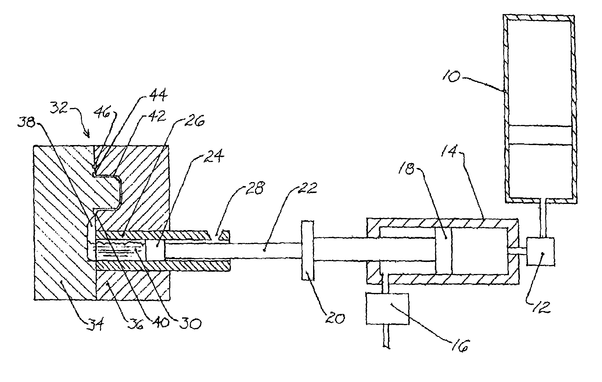
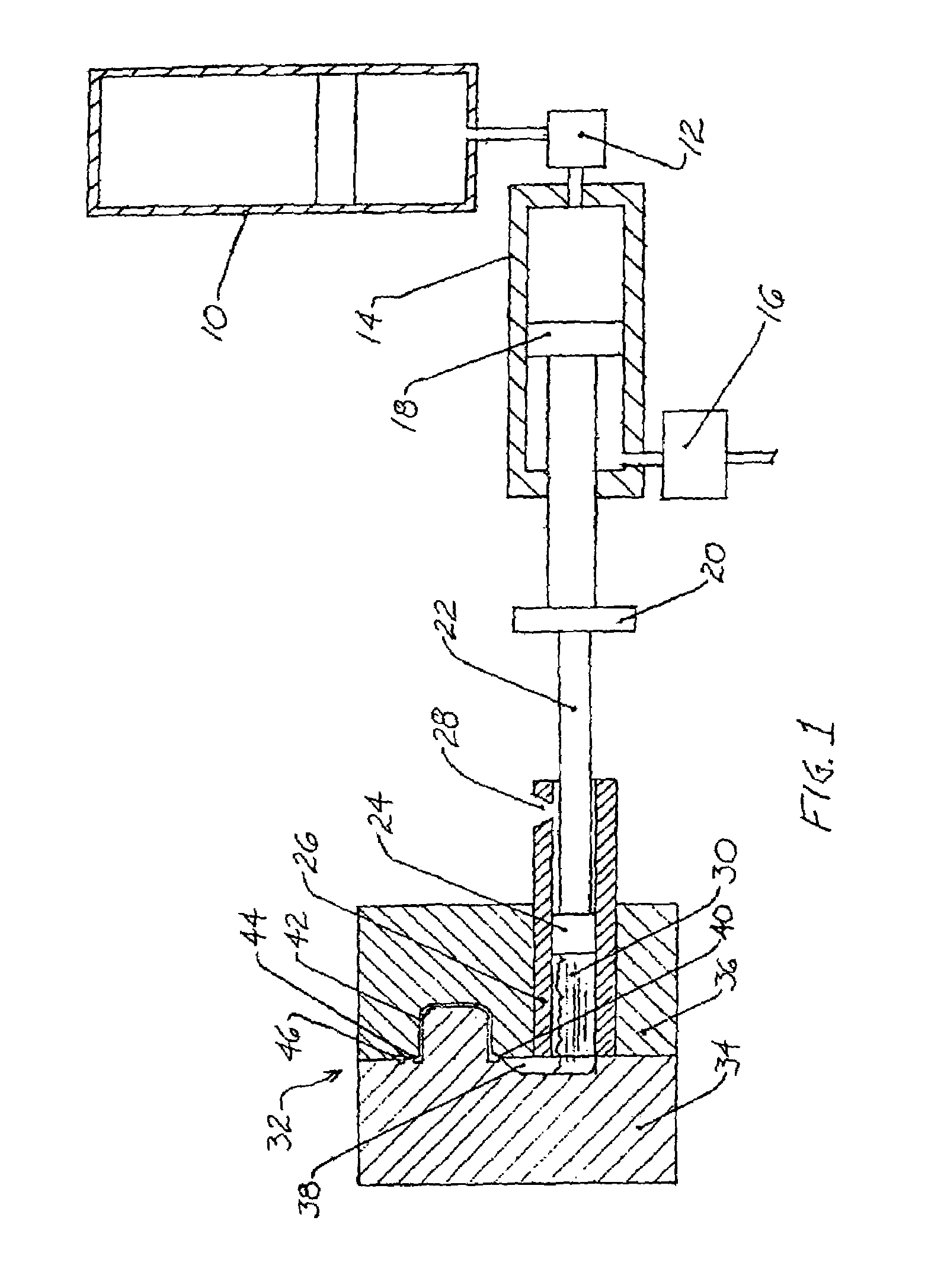
[0073]To illustrate the effect of the design techniques of the prior art for sizing overflow chambers and overflow gates, actual die casting machine parameters were used, including the following initial conditions and parameters:[0074]Weight of the piston, plunger, and tip=367 lbs[0075]Plunger velocity at impact=130 in / sec[0076]Piston diameter=7.00 in[0077]Piston rod diameter=4.00 in[0078]Plunger tip diameter=4.50 in[0079]Accumulator pressure=980 psi[0080]Cold chamber pressure at impact=709 psi[0081]Weight of the trimmed casting=1.15 lbs[0082]Number of main cavities in the mold=2[0083]Weight of the runner system=3.26 lbs[0084]Ratio of mold expansion to molten metal compression (Rac)=2.0[0085]Casting metal=Magnesium.
[0086]The following number and sizes of overflow chambers and gates were measured in a mold of the prior art:
[0087]
Chamber volumeGate cross-sectional(cubic in)area (sq in)Overflow #11.1360.050Overflow #21.1360.060Overflow #30.9470.050Overflow #41.1360.050Overflow #51.1360...
example 2
[0093]As a first step in illustrating the effect of the method of the present invention, the cross-sectional areas of the overflow gates of Example 1 were modified. Specifically, the parameters and overflow chamber volumes of Example 1 were retained, while the cross-sectional area of each gate of Example 1 was cut in half:
[0094]
Chamber volumeGate cross-sectional (cubic in)area (sq in)Overflow #11.1360.025Overflow #21.1360.031Overflow #30.9470.025Overflow #41.1360.025Overflow #51.1360.025Overflow #61.1360.030
The effect of this modification on the die casting system is presented in FIG. 6. The thick solid line, A6, represents the pressure of the molten metal in the main cavity of the mold, the line with short dashes, B6, represents the pressure of the molten metal in the runner, the line with the long dashes, C6, represents the velocity of the plunger, and the thin solid line, D6, represents the distance that the plunger traveled.
[0095]The reduction of the overflow gate areas substant...
example 3
[0096]Using the method of the present invention as described above, the initial conditions and parameters of Example 1 were used to size the volume of each overflow chamber and each overflow gate to reduce the pressure in the system below a maximum cavity pressure of 3,500 psi. To reiterate, the following initial data was used:[0097]Weight of the piston, plunger, and tip=367 lbs[0098]Plunger velocity at impact=130 in / sec[0099]Piston diameter=7.00 in[0100]Piston rod diameter=4.00 in[0101]Plunger tip diameter=4.50 in[0102]Accumulator pressure=980 psi[0103]Cold chamber pressure at impact=709 psi[0104]Weight of the trimmed casting=1.15 lbs[0105]Number of main cavities in the mold=2[0106]Weight of the runner system=3.26 lbs[0107]Ratio of mold expansion to molten metal compression (Rac)=2.0[0108]Casting metal=Magnesium.
[0109]As mentioned, a value of Pmax (the maximum desired cavity pressure) was chosen to be 3,500 psi. The following number and sizes of overflow chambers and gates were det...
PUM
| Property | Measurement | Unit |
|---|---|---|
| pressure | aaaaa | aaaaa |
| time | aaaaa | aaaaa |
| pressure | aaaaa | aaaaa |
Abstract
Description
Claims
Application Information
 - R&D
- Intellectual Property
- Life Sciences
- Materials
- Tech Scout
- Unparalleled Data Quality
- Higher Quality Content
- 60% Fewer Hallucinations
Browse by: Latest US Patents, China's latest patents, Technical Efficacy Thesaurus, Application Domain, Technology Topic, Popular Technical Reports.
© 2025 PatSnap. All rights reserved.Legal|Privacy policy|Modern Slavery Act Transparency Statement|Sitemap|About US| Contact US: help@patsnap.com


