Drop in clamp for wiring terminations

a technology for wiring terminations and clamps, which is applied in the direction of electrical connections, electrical connection structural associations, connections, etc., can solve the problems of difficult assembly of wiring terminations using automated assembly equipment, and achieve the effect of reducing the complexity of the manufacture of wiring devices and being easy to insert into or “dropped

Active Publication Date: 2007-02-13
LEVITON MFG
View PDF5 Cites 17 Cited by
  • Summary
  • Abstract
  • Description
  • Claims
  • Application Information

AI Technical Summary

Benefits of technology

[0006]The present invention discloses an improved clamp that can be assembled into a wiring device using automated manufacturing processes. The clamp can be easily inserted into or “dropped in” an electrical wiring device in a manner that is independent of an electrical wiring termination assembly thereby facilitating the automatic assembly of the wiring device and reducing the complexity of the manufacture of the wiring device. The clamp has a pair of legs spaced apart forming a U-shaped opening to allow the screw of the wiring termination assembly to be inserted therethrough but prevent the head of the screw from passing therethrough. The wiring device includes a wiring base modified to include support members to support the clamp legs and to permit the clamp to pivot about the support members independently of the wiring termination assembly.

Problems solved by technology

However, this type of wiring termination may be difficult to assemble using automated assembly equipment.

Method used


Image

  • Drop in clamp for wiring terminations
  • Drop in clamp for wiring terminations
  • Drop in clamp for wiring terminations

Examples


Embodiment Construction

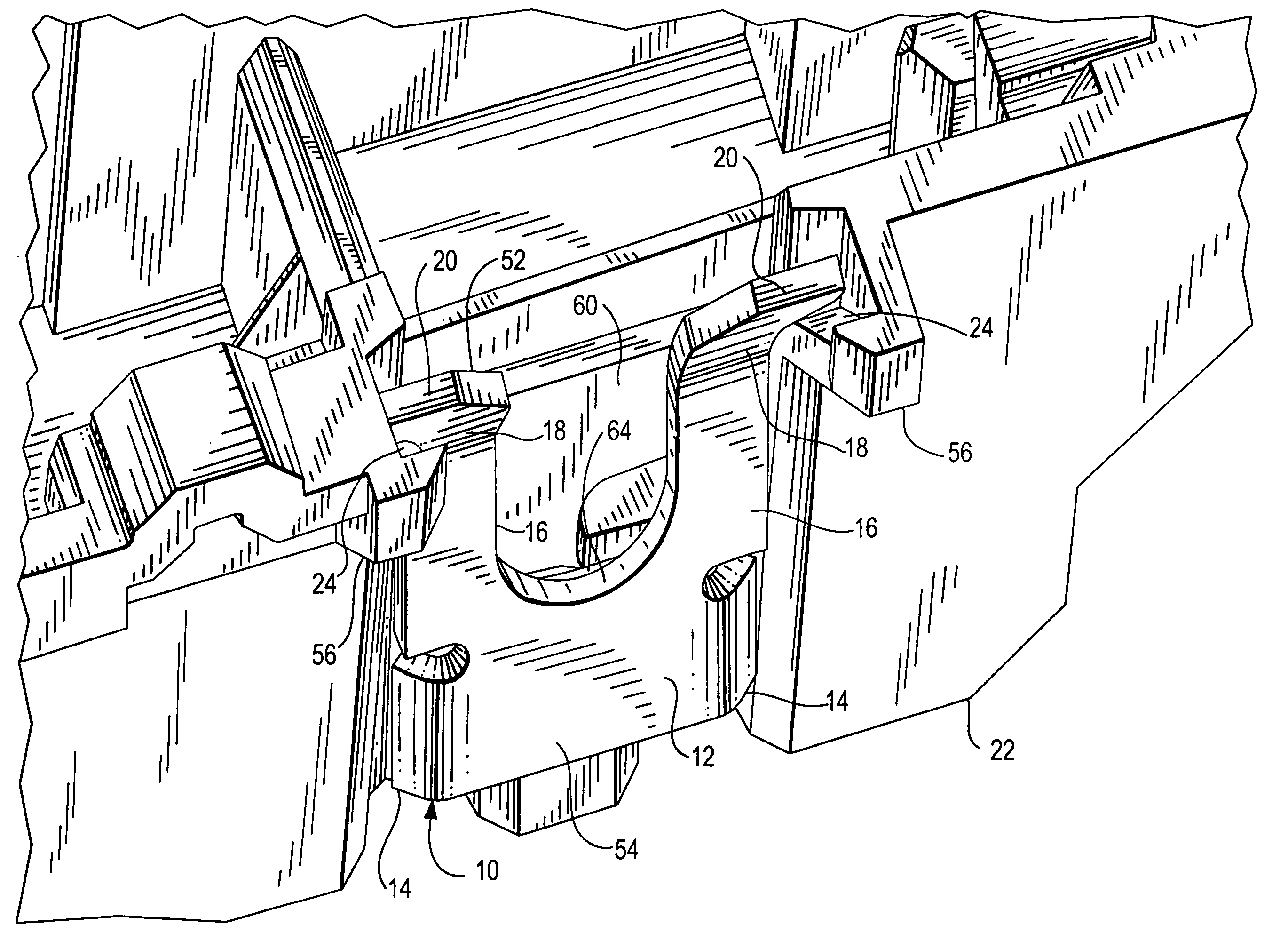
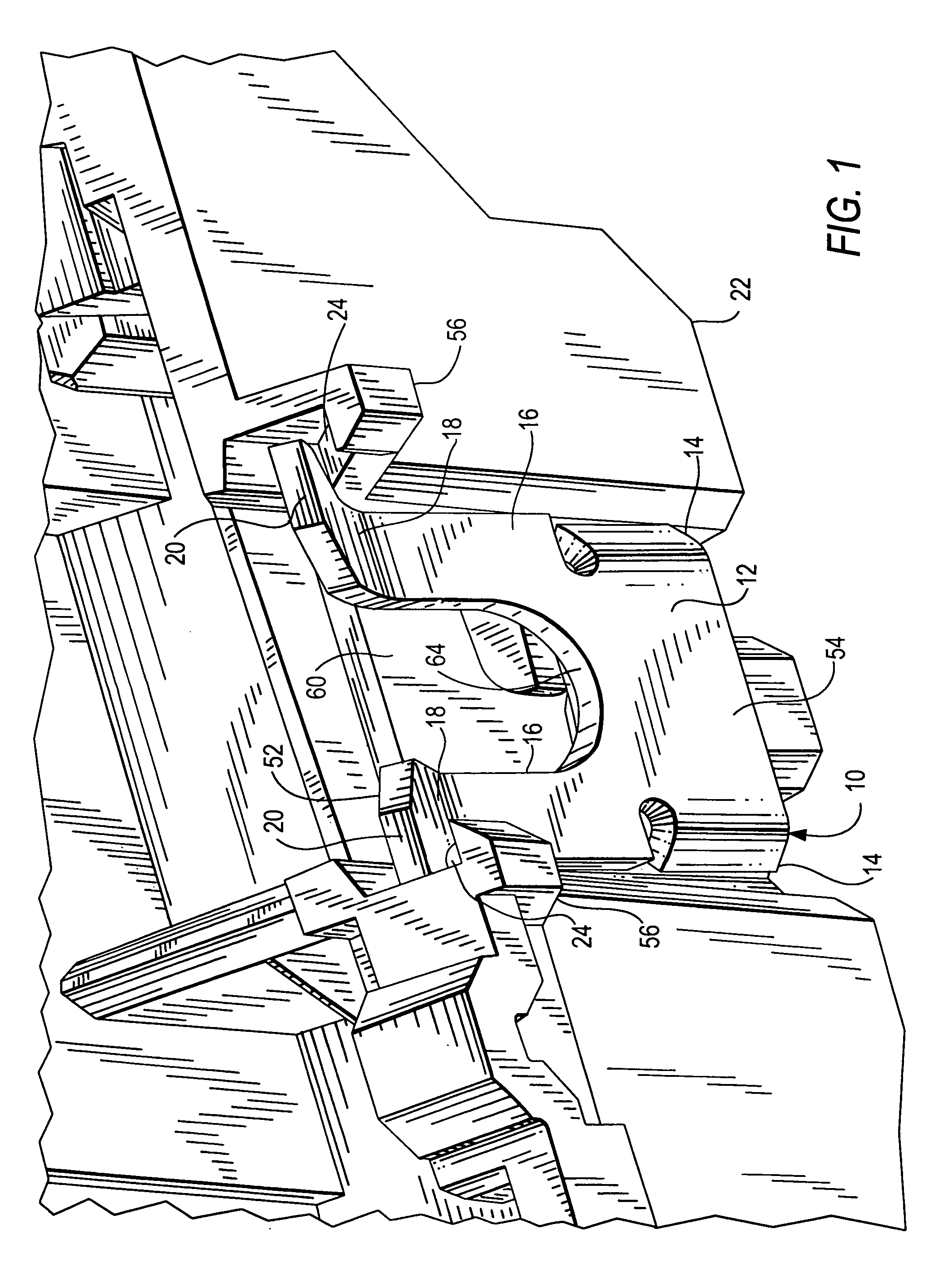
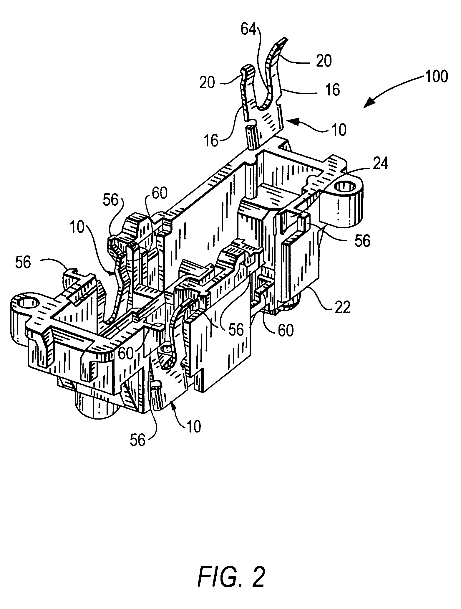
[0017]FIG. 1 illustrates an implementation of a clamp 10 for use with an electrical wiring that includes a wiring device base 22 which is formed by modifying a standard wiring device base to include a pair of support members 56 for supporting the clamp 10. The support members 56 are formed adjacent to a wiring termination recess 60 which holds both the clamp 10 and a wiring termination assembly 25 (FIG. 3). The clamp 10 can be easily inserted into the wiring termination recess 60 by automated assembly equipment independently of the wiring termination assembly which may help reduce the complexity and cost of the manufacture of a wiring device.

[0018]The clamp 10 includes a conductive plate 12 of brass, bronze etc. with a pair of legs 16 extending from a top edge of the plate 12. The free end of the legs 16 has a bend portion 18 to allow the legs to pivot about the wiring termination recess 60. Adjacent the bend portion 18 are tabs 20 extending away from the legs 16 to permit the legs ...


PUM


Abstract

An improved clamp that can be inserted into a wiring device independent of a wiring termination assembly thereby reducing the complexity and cost of the manufacture of the wiring device. The clamp has a pair of legs spaced apart forming an opening to allow the wiring termination assembly to be inserted therebetween. The wiring device includes support members to support the clamp legs so to permit the clamp to pivot about the support member independently of the wiring termination assembly.

Description

BACKGROUND OF THE INVENTION[0001]1. Field of the Invention[0002]The present invention relates to a clamp for use in electrical wiring terminations in electrical wiring devices such as receptacles and switches.[0003]2. Description of the Prior Art[0004]A typical household electrical wiring circuit includes electrical loads, such as lights, electrical appliances and other loads, connected to an alternating current (AC) power source originating from the electrical service panel of the home. Connected between the loads and the power source are power cables having conductors and electrical wiring devices such as switches and receptacles for controlling the power delivered to the loads. An electrical wiring device includes wiring terminations to allow the conductors of a cable to be electrically connected to the wiring device. One type of wiring termination is a combination of a movable clamping plate and a wiring termination assembly comprising a fixed contact pad and screw which allows ...

Claims


Application Information

Patent Timeline
Patent Type & Authority Patents(United States)
IPC IPC(8): H01R4/30
CPCH01R4/44H01R4/30
Inventor ALDERSON, DAVIDWILLIAMS, MICHAEL D.SCHMIDT, FREDMCCALLISTER, SHAWN
Owner LEVITON MFG
Why Eureka
Try Eureka