
Installation for producing non-woven textile webs with jet fluids leaving no visible mark

a technology of non-woven textiles and installations, applied in the direction of drying machines, drying, light and heating equipment, etc., can solve the problems of inability to produce non-woven textile webs. , to achieve the effect of improving the quality of textile webs, reducing the risk of aging, and reducing the production cos

Inactive Publication Date: 2007-02-20
RIETER PERFOJET
View PDF25 Cites 3 Cited by
  • Summary
  • Abstract
  • Description
  • Claims
  • Application Information

AI Technical Summary

Benefits of technology

[0018]The aim of the present invention is to provide an installation for producing nonwoven fibrous webs allowing the fibres of a nonwoven web to be entangled by means of water jets without having visible marks or impressions of the water jets in and on the surface of the nonwoven webs and without, however, requiring the hydraulic equipment to undergo movement.
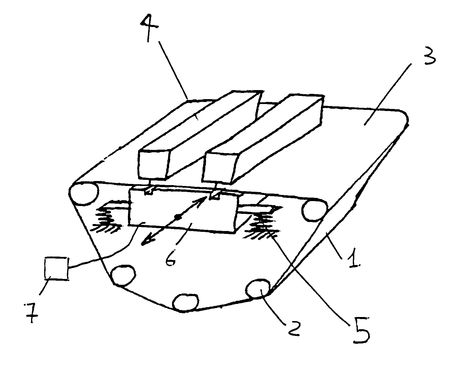
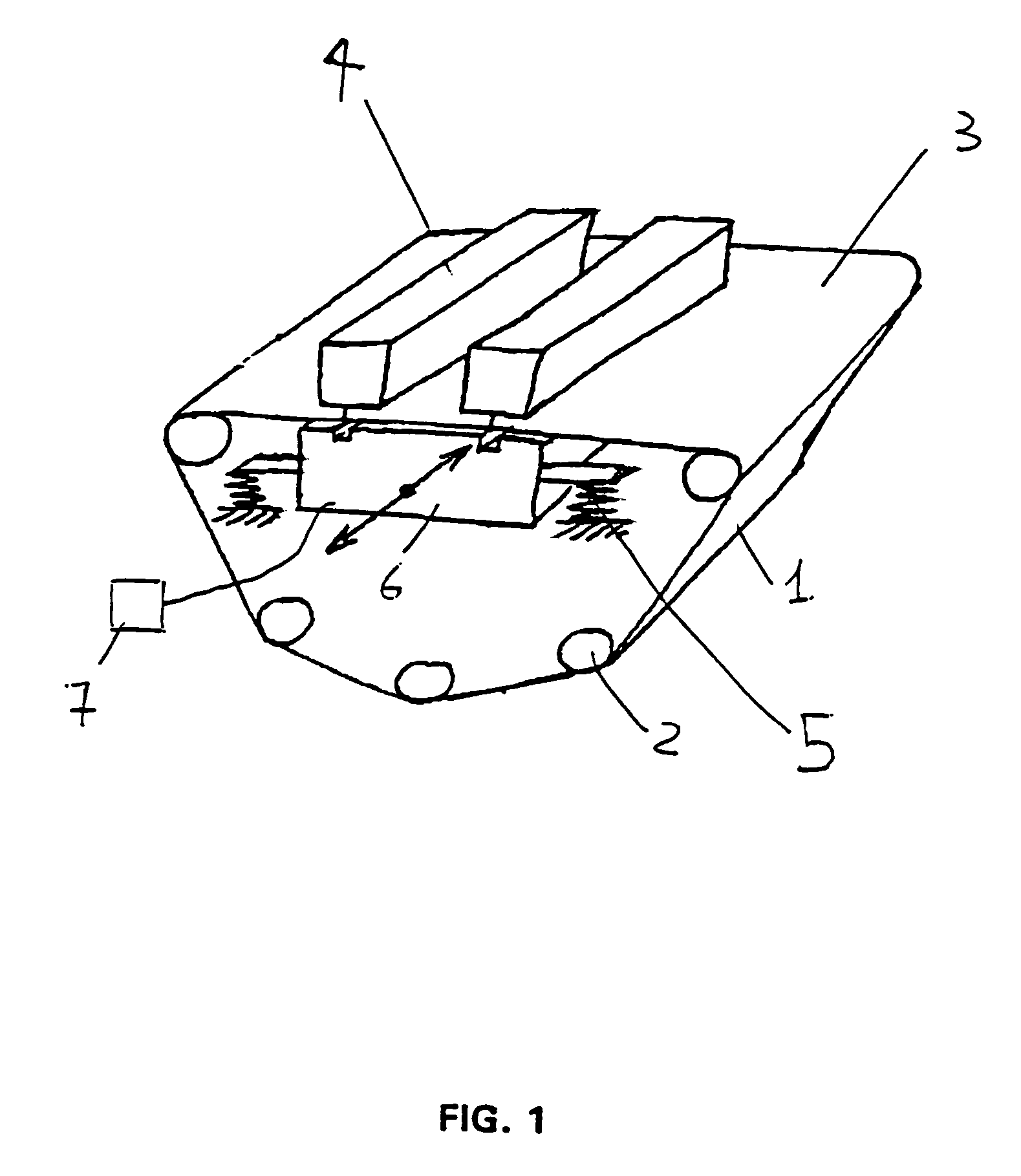
[0023]Owing to the effect of the vacuum created in the box, the conveyor is applied thereto and follows the movement thereof. Thus, a very simple means has been found to give the conveyor, and therefore the fibrous web that is pressed against it by the effect of the vacuum, an oscillatory movement while leaving the injector stationary. It is very much easier to impart an oscillatory movement on an essentially empty box which therefore does not weigh much than on the injector or even directly on the conveyor.
[0031]According to one embodiment, several injectors are associated with one and the same box. The fact that there is only a single oscillating box beneath several injectors, especially two or three injectors, avoids having two boxes undergoing their own movement, which could create undesirable harmonics.

Problems solved by technology

Although the conveyor is already moving and it is more difficult to impart an additional oscillatory movement on it than on the injector, the invention ignores this preconception however, by nevertheless making the conveyor oscillate, because it is now understood that an injector has hydraulic component can age prematurely and be likely to crack when subjected to vibrations, and, because of the high pressures involved, its repeated displacement is liable to cause dangerous leaks of fluid.
Injector oscillation techniques, like conveyor oscillation techniques, have the drawback of making very large masses move.
Devices allowing such large masses to move are extremely expensive.

Method used


Image

  • Installation for producing non-woven textile webs with jet fluids leaving no visible mark
  • Installation for producing non-woven textile webs with jet fluids leaving no visible mark
  • Installation for producing non-woven textile webs with jet fluids leaving no visible mark

Examples


Embodiment Construction

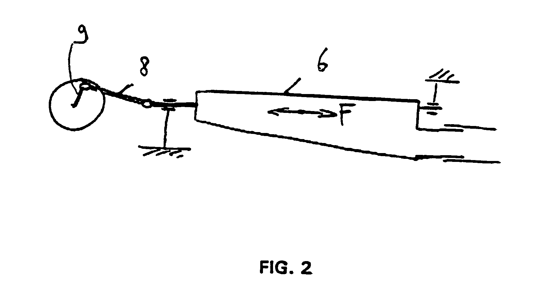
[0036]FIG. 1 is a schematic perspective view of an installation according to the invention. FIG. 2 illustrates a means intended to impart an oscillatory movement on the box. FIG. 3 illustrates an alternative embodiment.

[0037]The installation according to the invention, allowing nonwoven fibrous webs to be produced without leaving a mark, by jumbling of the lines, comprises an endless conveyor 1 passing over rolls 2 and having a top side 3 along which a nonwoven fibrous web (not shown) whose fibres have to be better entangled, passes. For this purpose, two banks of injectors 4 delivering 120 μm diameter water jets at 300 bar are provided. These jets are directed vertically onto the web 3 and, in that part plumb with the injectors 4, there are fifty jets per centimetre of web. Mounted on springs 5 beneath the top side 3 of the conveyor, and facing the injector 4, is a box 6 communicating with a vacuum source 7. The box is given, by means shown in FIG. 2, an oscillatory movement, indic...


PUM

PropertyMeasurementUnit
Pressureaaaaaaaaaa
Pressureaaaaaaaaaa
Diameteraaaaaaaaaa

Abstract

The invention concerns an installation for producing non-woven textile webs comprising a conveyor on one side of which the non-woven textile web passes between an injector and a vacuum chamber driven in an oscillating motion. The resulting web bears no mark.

Description

RELATED APPLICATIONS[0001]This application is the U.S. National Phase of PCT / FR01 / 03250 filed Oct. 19, 2001 and claims priority to French Patent Application No. 01 / 00526 filed Jan. 16, 2001, which is hereby incorporated by reference herein.BACKGROUND OF THE INVENTION[0002]1. Field of the Invention[0003]The invention relates to an improvement to installations for producing nonwoven fibrous webs, the cohesion of which is obtained by intermingling of fibres in the thickness of the said web by the action of small-diameter high-speed fluid jets, more particularly water jets.[0004]2. Description of the Related Art[0005]U.S. Pat. No. 3,906,130 relates to a perforated nonwoven. Moreover, in that document, oscillations are intended to promote the transverse deposition of the filaments and the formation of filament loops.[0006]FIG. 5 of that document also shows that the members delivering the water jets (reference 36) intended for consolidating the web of filaments are placed on a non-oscilla...

Claims


Application Information

Patent Timeline
IPC IPC(8): D04H1/46D04H18/04
CPCD04H18/04
Inventor NOELLE, FREDERICDUBUS, JEAN-MICHEL
Owner RIETER PERFOJET
Learn More