Gardening shears having energy-saving effect

a technology of energy-saving effect and gardening shears, which is applied in the field of pair of gardening shears, can solve the problems of inconvenience to users and waste of user's manual work, and achieve the effects of enhancing cutting force, saving energy, and reducing maintenance costs

Inactive Publication Date: 2007-02-20
DURACRAFT PRODS
View PDF5 Cites 27 Cited by
  • Summary
  • Abstract
  • Description
  • Claims
  • Application Information

AI Technical Summary

Benefits of technology

[0006]The primary objective of the present invention is to provide a pair of gardening shears having an energy-saving effect.
[0007]Another objective of the present invention is to provide a pair of gardening shears, wherein when the second cutting member is movable toward the first cutting member to perform the cutting action, the linking rod of the second cutting member pushes the first end of the first cutting member upward to drive the first cutting member to pivot about the drive arm of the mounting seat to push the first blade of the first cutting member downward, so that the first blade of the first cutting member is further movable toward the second blade of the second cutting member so as to enhance the cutting force of the first cutting member and the second cutting member, thereby enhancing the working efficiency of the gardening shears.
[0008]A further objective of the present invention is to provide a pair of gardening shears, wherein the gardening shears have a two-stage linkage action, so that the gardening shears can provide a larger cutting force, thereby facilitating a user performing the cutting action, and thereby greatly saving the user's manual work.
[0009]A further objective of the present invention is to provide a pair of gardening shears, wherein the linking rod of the second cutting member is movable in the adjusting slot of the first cutting member to adjust travel of the first cutting member, so that the first cutting member is movable smoothly.

Problems solved by technology

However, the cutting force of the blades 70 applied by the handles 80 is not large enough to cut a larger and harder workpiece, so that the user has to exert a larger force on the handles 80 so as to cut the larger and harder workpiece, thereby wasting the user's manual work, and thereby greatly causing inconvenience to the user when operating the gardening shears.

Method used


Image

  • Gardening shears having energy-saving effect
  • Gardening shears having energy-saving effect
  • Gardening shears having energy-saving effect

Examples


Embodiment Construction

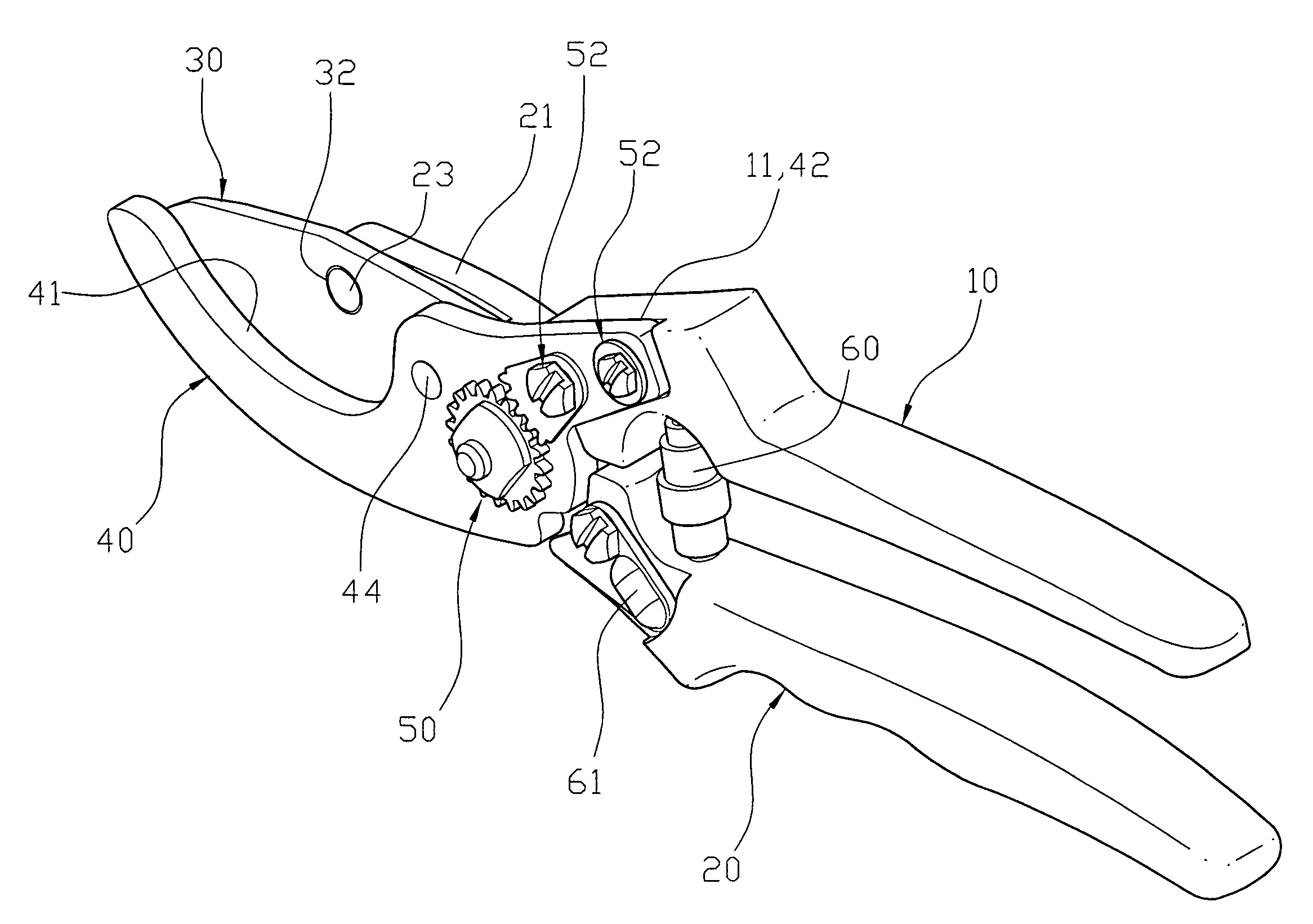
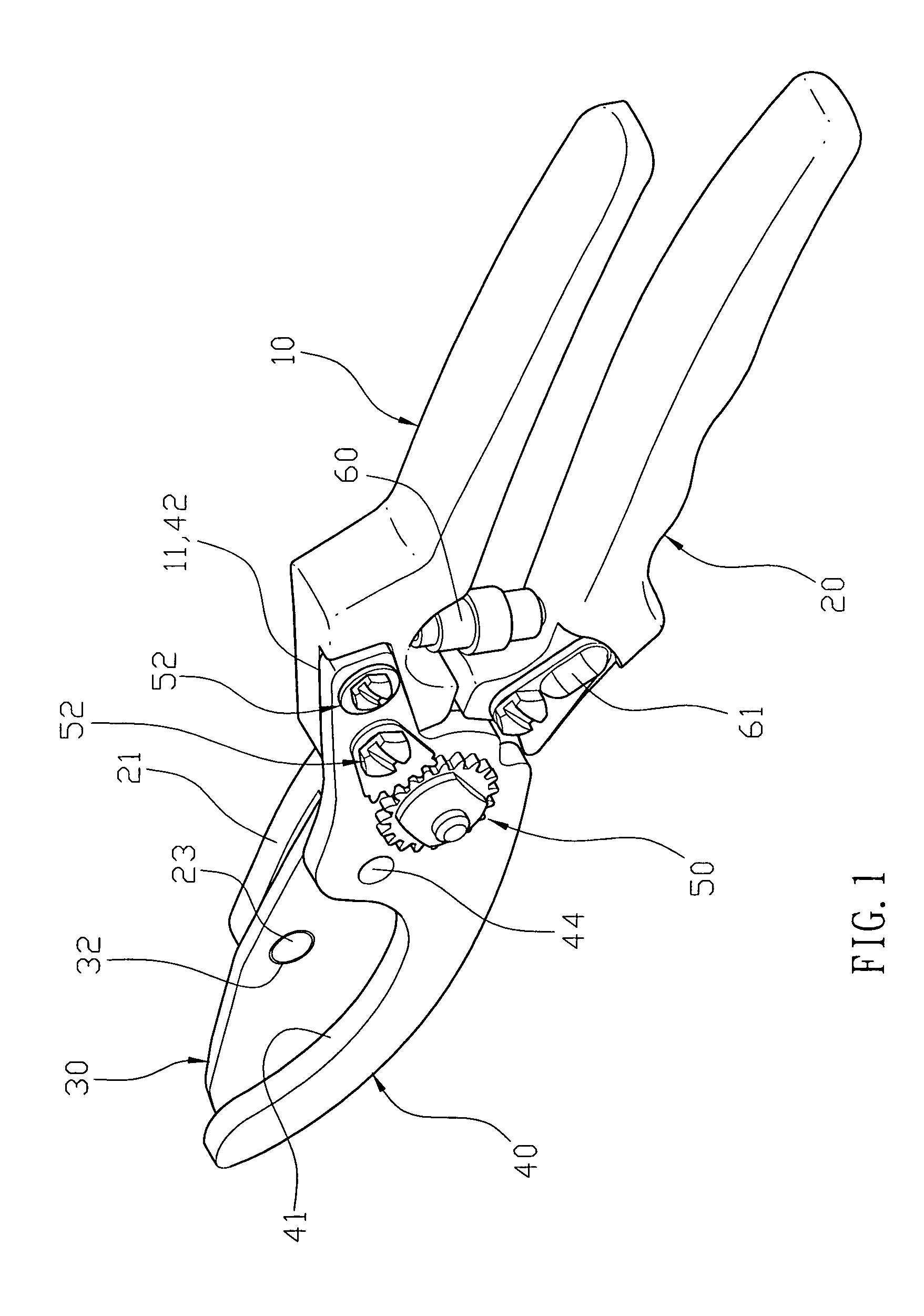
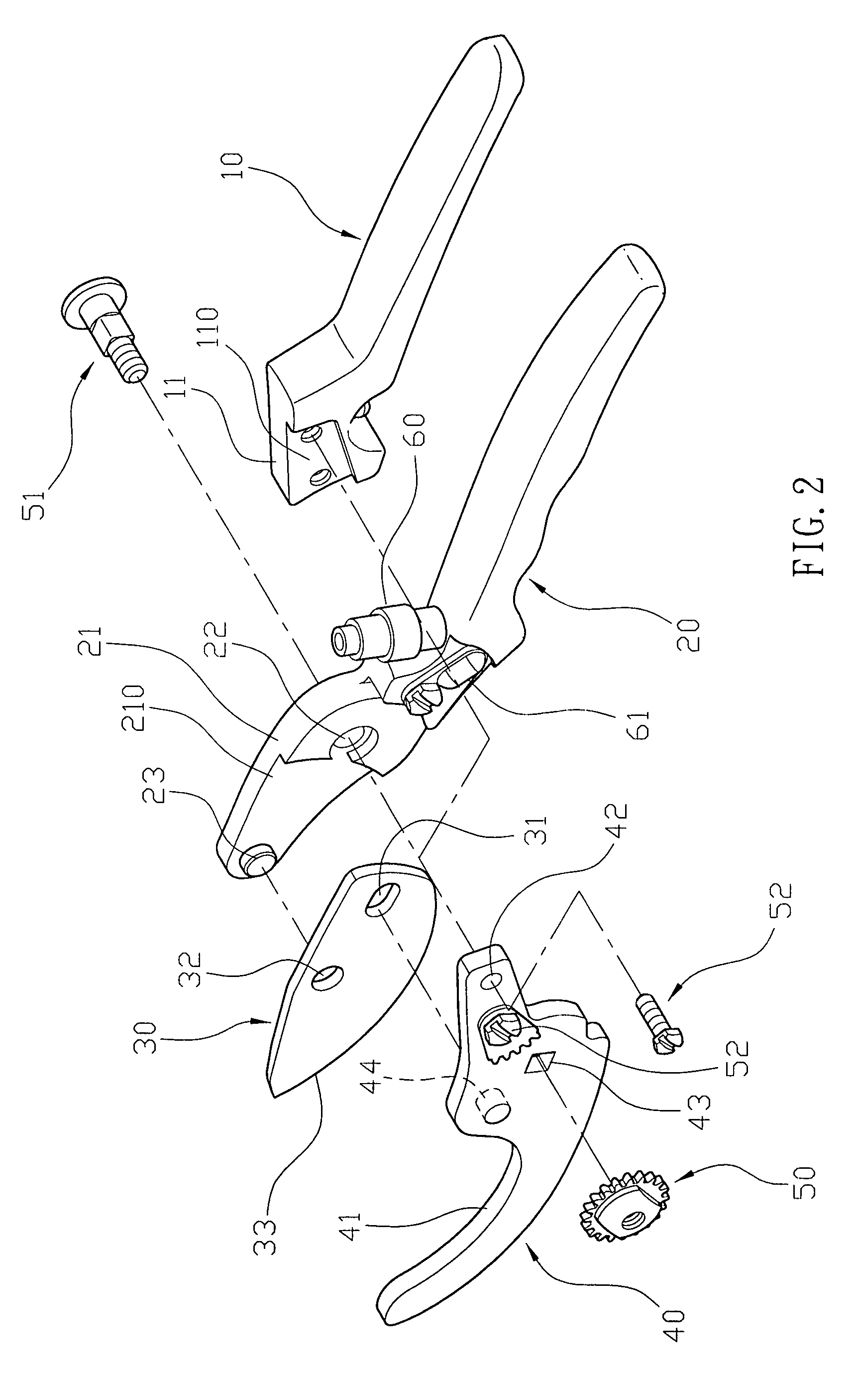
[0016]Referring to the drawings and initially to FIGS. 1–3, a pair of gardening shears in accordance with the preferred embodiment of the present invention comprise a first handle 20, a first cutting member 30, a second cutting member 40, and a second handle 10.

[0017]The first handle 20 has an end portion formed with a mounting seat 21. The mounting seat 21 has a first end formed with a pivot hole 22 located adjacent to the end portion of the first handle 20 and a second end formed with a drive arm 23. The mounting seat 21 has a recessed portion 210 for mounting the drive arm 23. The drive arm 23 is protruded outwardly from an inner side of the recessed portion 210 of the mounting seat 21.

[0018]The first cutting member 30 is pivotally mounted on the mounting seat 21 and has a first end formed with an adjusting slot 31, a mediate portion formed with a pivot bore 32 pivotally mounted on the drive arm 23 of the mounting seat 21 and a second end protruded outwardly from the mounting sea...


PUM


Abstract

A pair of gardening shears include a first handle, a first cutting member, a second cutting member, and a second handle. Thus, when the second cutting member is movable toward the first cutting member to perform the cutting action, the linking rod of the second cutting member pushes the first cutting member to drive the first cutting member to pivot about the drive arm of the mounting seat to push the first blade of the first cutting member downward, so that the first blade of the first cutting member is further movable toward the second blade of the second cutting member so as to enhance the cutting force of the first cutting member and the second cutting member thereby enhancing the working efficiency of the gardening shears.

Description

BACKGROUND OF THE INVENTION[0001]1. Field of the Invention[0002]The present invention relates to a pair of gardening shears and, more particularly, to a pair of gardening shears having an energy-saving effect.[0003]2. Description of the Related Art[0004]A pair of conventional gardening shears in accordance with the prior art shown in FIG. 5 comprise two handles 80 pivotally connected with each other by a pivot shaft 7 and each having a distal end formed with a blade 70. Thus, when a user exerts a force on the two handles 80, the two handles 80 are movable toward each other, so that the blades 70 of the handles 80 are movable toward each other to perform a cutting action so as to cut a workpiece, such as the branch or the like. In such a manner, the handles 80 perform a linkage action by the length of each of the handles 80, so that the blades 70 of the handles 80 have a force to perform the cutting action. However, the cutting force of the blades 70 applied by the handles 80 is not ...

Claims


Application Information

Patent Timeline
Patent Type & Authority Patents(United States)
IPC IPC(8): B26B13/00
CPCA01G3/02
Inventor LEE, MIKE C.
Owner DURACRAFT PRODS
Why Eureka
Try Eureka