Determination of maximum allowable humidity in indoor space to avoid condensation inside building envelope

a technology of indoor space and humidity, applied in the field of indoor central heating, ventilation and air conditioning (hvac) systems, can solve the problems of less insulation, less insulation, and the proportion of buildings that are affected by condensation, and achieve the effect of preventing condensation

Active Publication Date: 2007-02-20
CARRIER CORP
View PDF3 Cites 20 Cited by
  • Summary
  • Abstract
  • Description
  • Claims
  • Application Information

AI Technical Summary

Benefits of technology

[0004]Therefore, during the winter months, the cold outdoor air has a relatively low moisture content, however, the air inside building structures is typically heated. Depending on the construction quality of a particular building, some of the cold dry outside air infiltrates into the warm indoor space and is subsequently heated to the indoor temperature. This phenomenon effectively reduces the indoor relative humidity and the indoor air becomes very dry.
[0006]Buildings typically have thermally insulated walls and attics to minimize heat loss and reduce cold air infiltration. However, portions of the building envelope, such as windows, may be less insulated than others, and their interior surfaces may get colder. If the outdoor temperature is low enough and the indoor humidity high enough, moisture may condense on these less insulated interior surfaces, which is undesirable. Conversely, some buildings in colder climates are built to be extremely “tight” allowing minimal outdoor air infiltration levels. Without the natural drying due to outside air infiltration, internal moisture generated by the occupants and their activities allows the indoor relative humidity to reach high levels resulting in condensation even in the winter months.
[0011]This invention uses known data regarding the psychometric characteristics of air to achieve accurate indoor relative humidity control to prevent condensation without complex mathematical computational requirements.

Problems solved by technology

However, portions of the building envelope, such as windows, may be less insulated than others, and their interior surfaces may get colder.
If the outdoor temperature is low enough and the indoor humidity high enough, moisture may condense on these less insulated interior surfaces, which is undesirable.
Without the natural drying due to outside air infiltration, internal moisture generated by the occupants and their activities allows the indoor relative humidity to reach high levels resulting in condensation even in the winter months.
However, as weather patterns change, frequent manual adjustment is often required.
To date there has been no way for the occupant to know exactly how much to adjust the humidity setting.
This continual trial and error process results in the indoor relative humidity level either being too high or too low in comparison with the ideal indoor humidity level.
Therefore, controlling indoor relative humidity to a fixed relative humidity level, as with a simple humidistat, is undesirable.
While systems have been proposed to perform detailed calculations of a maximum relative humidity level, the known proposed are quite complex.

Method used


Image

  • Determination of maximum allowable humidity in indoor space to avoid condensation inside building envelope
  • Determination of maximum allowable humidity in indoor space to avoid condensation inside building envelope
  • Determination of maximum allowable humidity in indoor space to avoid condensation inside building envelope

Examples


Embodiment Construction

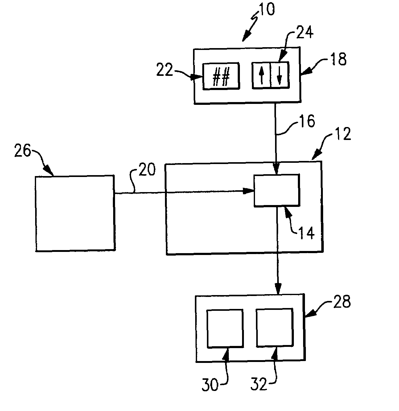
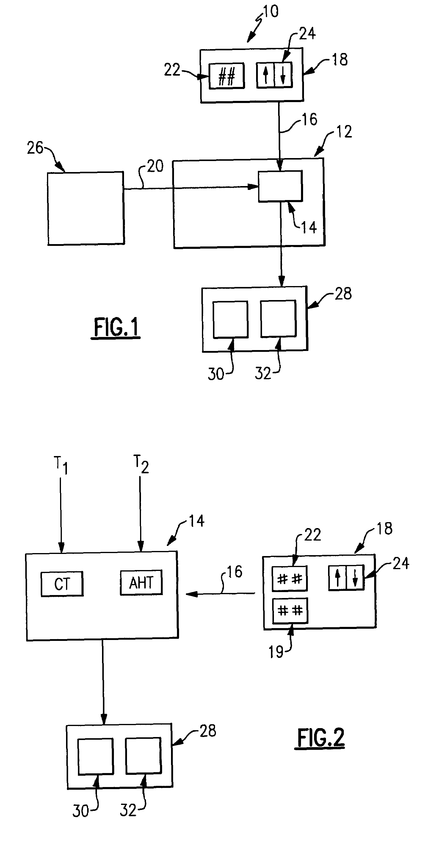
[0022]A schematic view of a building HVAC system 10 is illustrated in FIG. 1. An indoor control unit 12 includes central control 14 which is operable to receive a user input 16 from a user interface 18 and at least one environmental input 20. The user input 16 is a heating humidity level 22 which is selected from a predetermined range. As shown, the level is adjusted by pressing up / down arrows 24 on the user interface 18. Of course other input devices can be utilized. An outdoor unit 26 is operable to transmit the environmental input 20 to the central control 14.

[0023]The central control 14 then calculates a desired indoor relative humidity based upon the user input 16 and the environmental input 20 and adjusts an actual indoor relative humidity to a value proximate the calculated desired indoor relative humidity by selectively activating / deactivating at least one indoor device 28. As is known, the indoor device 28 could be a humidifier 30, and / or a ventilator 32, or other humidity ...


PUM


Abstract

Known psychometric characteristics of air are employed to achieve accurate indoor relative humidity control to prevent condensation inside a building envelope without complex mathematical computational requirements. An HVAC system control includes a simple control algorithm employed to calculate an effective delta (ΔT) based upon a single adjustment factor (A*) and environmental inputs. The effective delta (ΔT) is then used to determine a maximum allowable indoor relative humidity. The system control is then operable to selectively activate / deactivate a device to adjust an actual indoor relative humidity to a value less than the maximum allowable indoor relative humidity to prevent condensation inside the building envelope.

Description

BACKGROUND OF THE INVENTION[0001]The application claims priority to U.S. Provisional Application No. 60 / 537,527 which was filed on Jan. 20, 2004, the disclosure of which is incorporated in its entirety herein by reference.[0002]This application relates to an indoor central heating, ventilation, and air conditioning (HVAC) system wherein various units report environmental characteristics to a central control for evaluation in relation to a user input. The central control controls an indoor relative humidity to prevent condensation inside a “building envelope.” A building envelope is defined to include all building exterior walls, i.e., walls having a side exposed to the outside elements and the roof.[0003]Relative humidity is defined as the ratio of the actual amount of moisture in the air to the maximum moisture capacity at a given air temperature. It is known that as temperature increases, the capacity of the air to hold moisture in the form of water vapor also increases. Conversel...

Claims


Application Information

Patent Timeline
Patent Type & Authority Patents(United States)
IPC IPC(8): F25B49/00F24F11/00F25D17/04
CPCF24F11/0008F24F11/0015F24F11/0012F24F2011/0063F24F2011/0013F24F11/30F24F2110/10F24F2110/12F24F2110/20F24F11/64F24F11/62F24F11/50
Inventor SHAH, RAJENDRA K.
Owner CARRIER CORP
Why Eureka
Try Eureka