Headgear for noninvasive ventilation interface

a ventilation interface and headgear technology, applied in the field of adjustable, semi-rigid headgear, can solve the problems of significant patient discomfort and irritation, headgear used with these interface devices, harnesses, headbands,

Inactive Publication Date: 2007-02-20
VENTLAB
View PDF14 Cites 118 Cited by
  • Summary
  • Abstract
  • Description
  • Claims
  • Application Information

AI Technical Summary

Benefits of technology

[0010]The present invention is directed to a headgear for noninvasive ventilation interface made up of a nasal cannula and tubing having a given outside diameter, and a headgear yoke with curved ends including tubing retainers. The yoke is adapted to extend transversely over a wearer's head and includes side sections with top and bottom ends and a top section connectable to the side section top ends. Preferably, the yoke is adjustable in length. For example, in one embodiment the headgear yoke includes spaced index notches near the top end of at least one of its side sections along with at least one side section receiving slot within the yoke top section. The yoke top section also includes at least one index notch lock having locking and unlocking positions usable to secure or release the at least one indexed side section. The sections of the headgear yoke are semi-rigid and lightweight. Suitable construction materials for the headgear yoke include, but are not limited to metal such as aluminum alloy and plastics such as polyvinyl chloride and nylon. Preferably, the headgear yoke sections are molded from a single type of material, but the yoke section could also be made of composite materials. For example, the yoke top section can be made from metal and the side sections rigid plastic or vice versa. The headgear yoke is semi-rigid in that the yoke is flexible and therefore is bendable and twistable, but is neither longitudinally elastic nor compressible.
[0013]A mating element for each of the C-shaped tubing retainers is included to prevent the tubing from kinking near the C-shaped tubing retainers. Each retainer mating element has an elbow section with an open side and a clip section connected to the elbow section by a rigid beam having a length substantially equal to the C-shaped retainer given length, wherein both of the sections have an inside diameter substantially equal to the tubing given outside diameter for receiving the tubing's outside diameter. These retainer mating elements are mateable with the C-shaped tubing retainers to capture and direct the tubing from in back of the wearer's head to along the sides of the wearer's face whenever the headgear yoke is worn extending transversely over the wearer's head. The tubing may be directed behind the wearer's head and downwardly, or behind the wearer's head and upwardly. Alternatively, the tubing may be directed downwardly but in front of the wearer' neck and chest.

Problems solved by technology

There are problems with typical headgear used with these interface devices.
Many patients find the harness, headband, or other headgear used to keep the mask in position uncomfortable, particularly when sleeping.
The headband or harness must typically maintain the interface device against the face or nose of the wearer with some pressure, resulting in significant patient discomfort and irritation.
While this type of headband apparatus may be adequate for some patients, others will no doubt find the headband too uncomfortable for long term use because of restriction to blood vessels in their forehead region.
Moreover, Burns does not teach a means to prevent the cannula tubing from kinking caused by the wearer's movements.
As with Burns, some patients will find this type of tubing fastening apparatus to be too restrictive to be comfortable.
Moreover, Correa et al does not disclose a means to direct medical gas tubing such that it does not kink as the wearer changes positions while sleeping, etc.
Additionally, fabric or elastic headbands or headgear often become tangled and twisted, and are therefore difficult for the user to easily place on the user's head.
Lastly, the prior art headgear causes significant difficulty in properly locating the interface device on the wearer and requires significant adjustment.

Method used


Image

  • Headgear for noninvasive ventilation interface
  • Headgear for noninvasive ventilation interface
  • Headgear for noninvasive ventilation interface

Examples


Embodiment Construction

[0020]In the following description, terms such as horizontal, upright, vertical, above, below, beneath and the like are used solely for the purpose of clarity in illustrating the invention and should not be taken as words of limitation. The drawings are for the purpose of illustrating the invention and are not intended to be to scale.

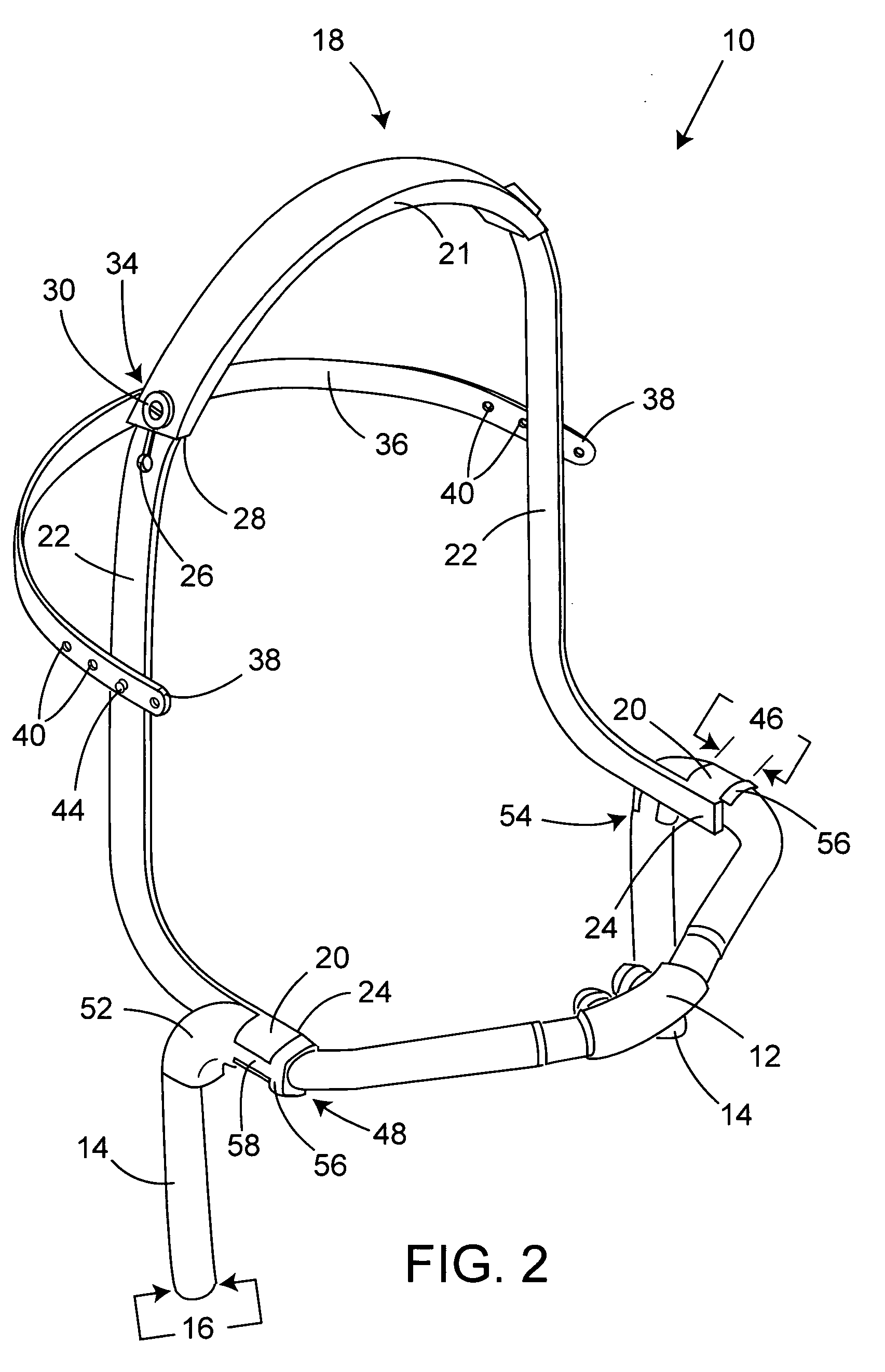
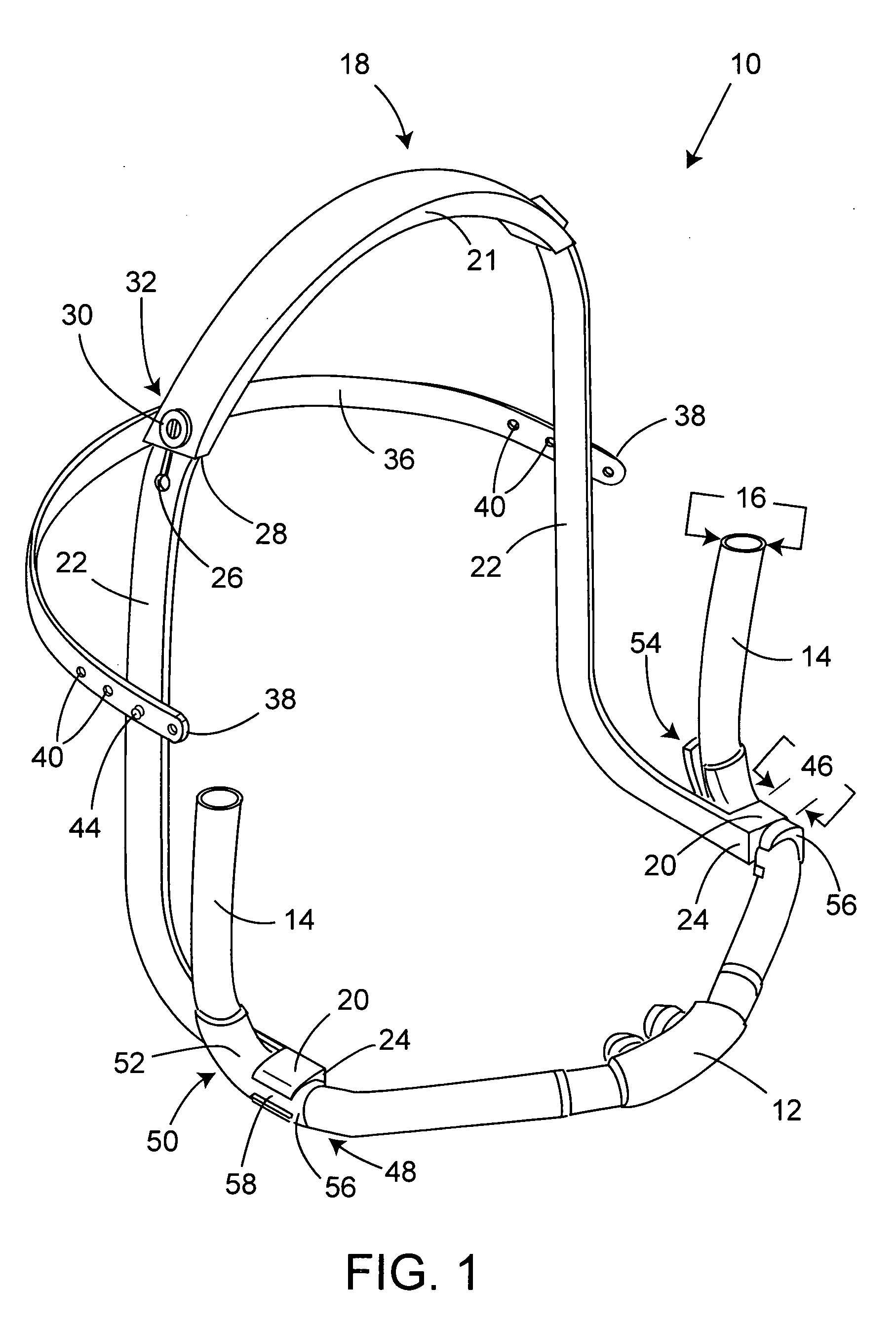
[0021]Referring to the drawings and first to FIGS. 1 and 2, a headgear for noninvasive ventilation interface 10, comprises a nasal cannula 12 including cannula tubing 14 having a given outside diameter 16; and a headgear yoke 18 with ends including cannula tubing retainers 20. In particular, headgear yoke 18 includes a top section 21 and side sections 22 with lower ends 24. Moreover, headgear yoke 18 includes spaced index notches 26 near the top end of at least one of its side sections 22 along with at least one side section receiving slot 28 within yoke top section 21. The yoke top section 21 also includes at least one index notch lock 30 having an unl...


PUM


Abstract

The present invention is a headgear for noninvasive ventilation interface made up of a nasal cannula including cannula tubing having a given outside diameter, and a headgear yoke with ends including tubing retainers. The yoke is adapted to extend transversely over a wearer's head. The tubing retainers are C-shaped projections having a given length and an inside diameter substantially equal to the tubing outside diameter. The present invention further includes a retainer mating element for each of the C-shaped tubing retainers to prevent the tubing from kinking near the C-shaped tubing retainers. The retainer mating element has an elbow section with an open side and a clip section connected to the elbow section by a rigid beam having a length substantially equal to the C-shaped tubing retainer given length, wherein both of the sections have an inside diameter substantially equal to the tubing given outside diameter.

Description

BACKGROUND OF THE INVENTION[0001](1) Field of the Invention[0002]The present invention relates to an adjustable, semi-rigid headgear for maintaining the proper positioning of a headgear for a noninvasive ventilation interface about a wearer's head and on the wearer's face. In particular, the present invention prevents the kinking of medical gas tubing and holds a nasal cannula in proper position as the wearer sleeps and / or changes their head's position.[0003](2) Description of the Prior Art[0004]There are certain medical situations in which it is necessary or desirable to deliver a flow of breathing gas to the airway of a patient without intubating the patient or surgically inserting a tube in the patient's trachea. For example, a patient might be ventilated using a technique known as non-invasive ventilation. Non-invasive ventilation interfaces are also used with patients having a medical disorder such as sleep apnea who might require continuous positive airway pressure (CPAP) or B...

Claims


Application Information

Patent Timeline
Patent Type & Authority Patents(United States)
IPC IPC(8): A61M15/08A62B7/00
CPCA61M16/0666A61M16/0683A62B18/084
Inventor LAU, GREG Y.REED, CHRISTOPHER B.
Owner VENTLAB
Why Eureka
Try Eureka