Vehicle air bag door

a technology for air bags and doors, applied in the direction of vehicular safety arrangments, pedestrian/occupant safety arrangements, vehicle components, etc., can solve the problems of deformation or breakage of the hinge section, inability to widely open the door section, and the door section might be bent downward and broken, so as to improve the reinforcement effect of the plate section, prevent cracking or scattering of the extension, and increase the stiffness of the extension itsel

Active Publication Date: 2007-02-20
DAIKYONISHIKAWA CORP
View PDF21 Cites 53 Cited by
  • Summary
  • Abstract
  • Description
  • Claims
  • Application Information

AI Technical Summary

Benefits of technology

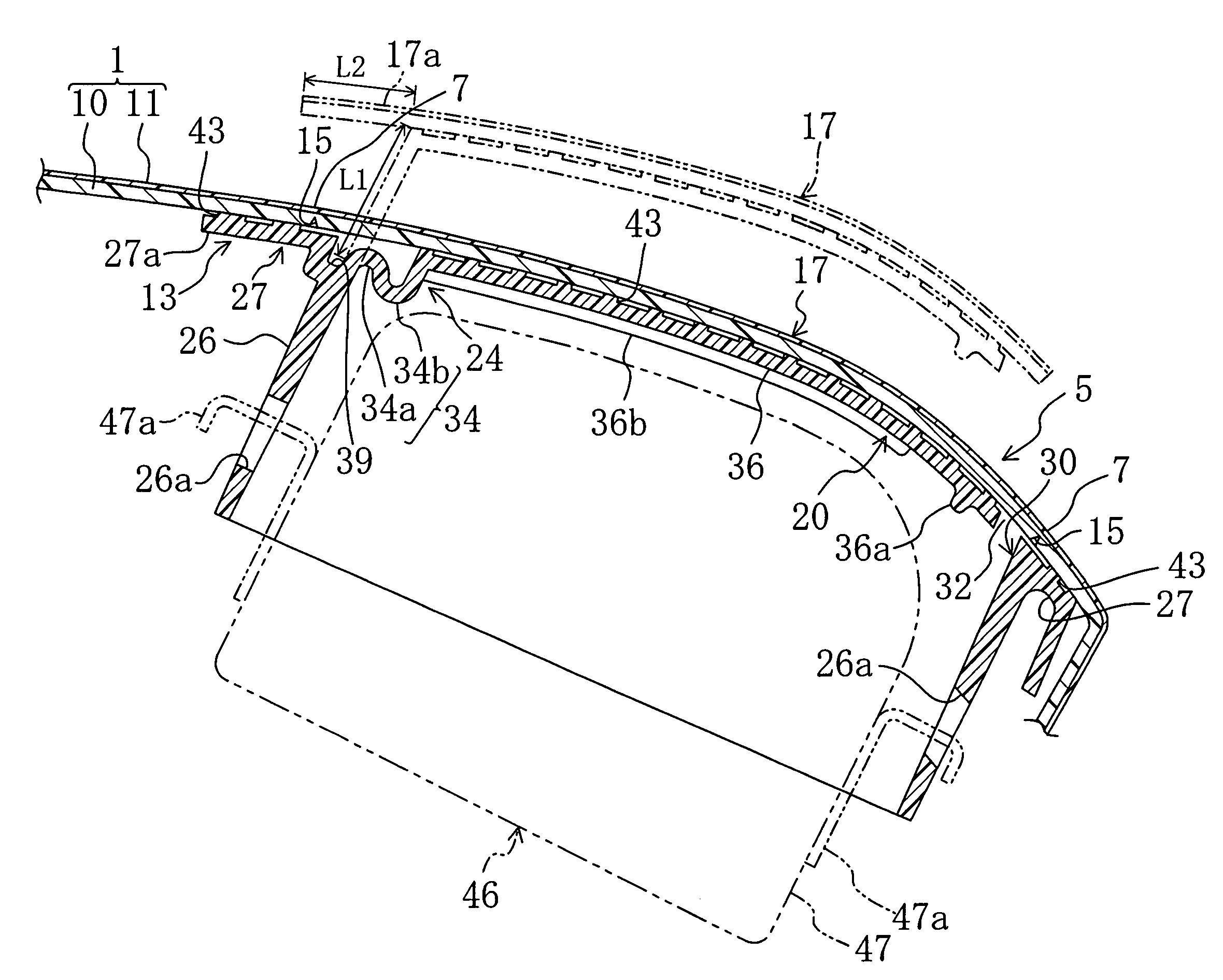
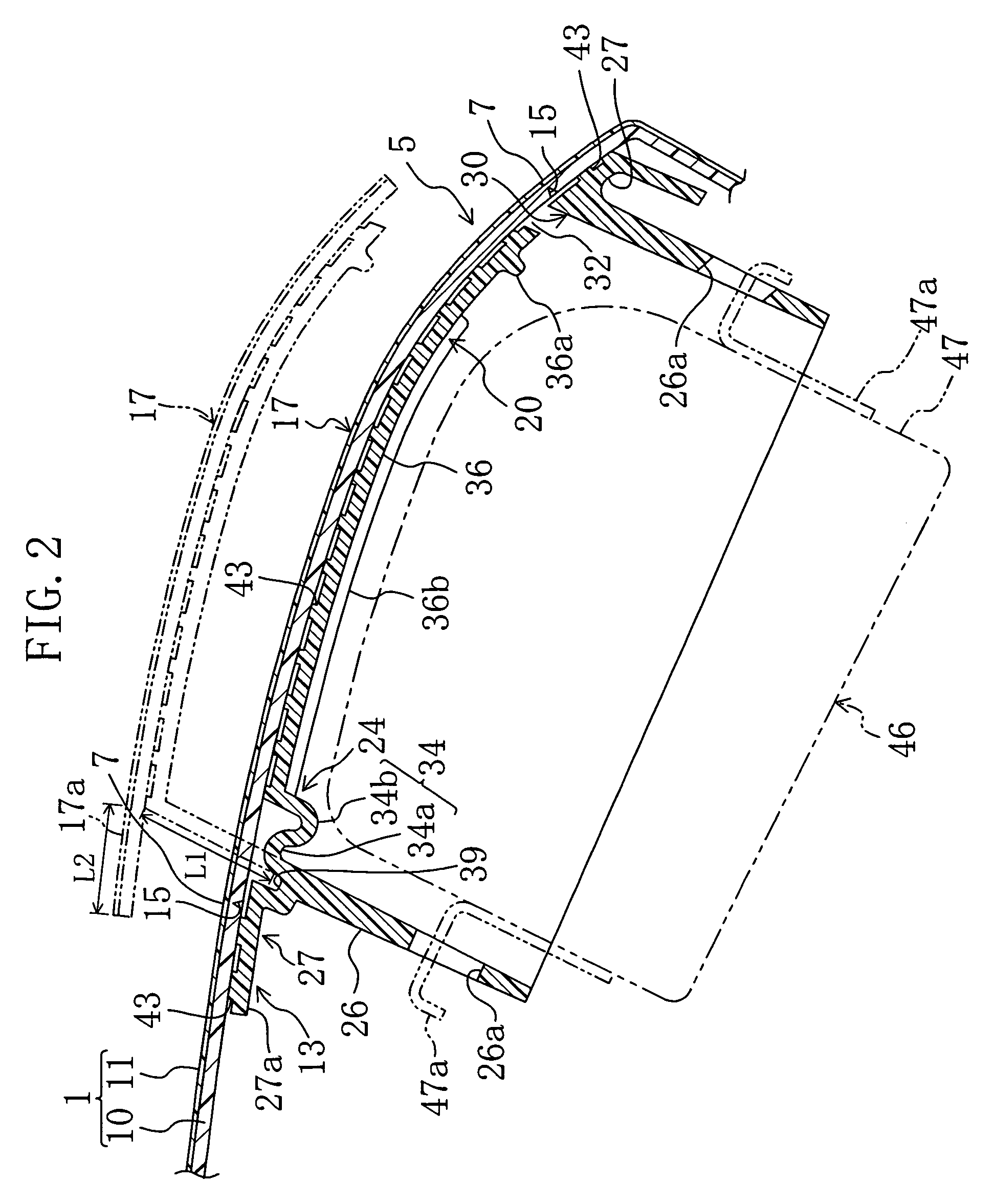
[0025]In such an embodiment, the plate section is provided with the extensions that are located outwardly of both the longitudinal ends of the hinge section and are extended from the plate section main body to the vicinities of the corners of the shooting aperture at the outer edge thereof. Therefore, by welding the extensions of the plate section to the panel main body, the reinforcing effect of the plate section can be further enhanced in the vicinities of the gaps formed outwardly of both the longitudinal ends of the hinge section and between both the longitudinal ends and the outer edge of the shooting aperture. Furthermore, the ribs, provided in the vicinities of both the longitudinal ends of the hinge section, are extended to the extensions of the plate section, and the ribs are formed continuously from the hinge section to the extensions. Therefore, the stiffness of the extensions themselves is increased due to the ribs, and thus cracking or scattering of the extensions can be prevented when the door section is turned.

Problems solved by technology

However, since the hinge section is formed into an approximate U-shape and the door section is opened by pivoting the hinge section, the door section and the panel main body interfere with each other, which makes it impossible to widely open the door section.
However, the door flap violently collides against a door-section-side edge of the panel main body, and therefore, the hinge section might be deformed or broken.
In addition, since the hinge section is thin, the door section might be bent downward and broken when a load is applied to an instrument panel from above.
Furthermore, such a problem might similarly occur in the case where the hinge section is formed into a thin U-shape.

Method used


Image

  • Vehicle air bag door
  • Vehicle air bag door
  • Vehicle air bag door

Examples


embodiment 2

[0070]In Embodiment 2, as shown in FIG. 5, a back-up member 13 includes a first molded part 51 and a second molded part 53. The first molded part 51 is made of a first resin material, and constitutes a back-up section 27. The first molded part 51 is integrally formed with a rectangular tubular section 26 extending from a shooting aperture 30 within the back-up section 27 and away from the panel main body 1. At the inner side of the tubular section 26, a front-side portion 51a of the tubular section 26 is integrally formed with a hinge-side extension 53a of the second molded part 53. The second molded part 53 is made of a second resin material similar to or different from the first resin material used for the first molded part 51, and constitutes a plate section 20, a hinge section 24 and the hinge-side extension 53a which are integrally formed so as to have an approximate L-shape in cross section.

[0071]According to Embodiment 2, both the molded parts 51 and 53 are provided by a so-c...

embodiment 3

[0081]FIGS. 6 through 8 illustrate Embodiment 3 of the present invention. It should be noted that in the present embodiment, the same constituting elements as those described in Embodiments 1 and 2 are identified by the same reference characters, and the detailed description thereof will be omitted.

[0082]In Embodiment 3, as shown in FIGS. 6 through 8, ribs 40 are integrally formed with a hinge section 24. Each rib 40 is protruded from the bottom face of an associated one of longitudinal ends of the hinge section 24 (which is opposite to a door section 17). Each rib 40 is formed continuously across first and second curved portions 34a and 34b of the hinge section 24 so as to extend along both the curved portions 34a and 34b. Further, each rib 40 has a rib extension 40a that extends from one end of the rib 40 to reach a base end of a plate section main body 36, and straddlingly extends to an inner end of an associated one of extensions 38. In other words, each rib 40 is formed continu...

embodiment 4

[0095]In Embodiment 4, as shown in FIG. 10, a back-up member 13 includes a first molded part 51 and a second molded part 53. The first molded part 51 is made of a first resin material, and constitutes a back-up section 27. The first molded part 51 is integrally formed with a rectangular tubular section 26 extending from a shooting aperture 30 within the back-up section 27 and away from the panel main body 1.

[0096]The second molded part 53 is made of a second resin material that is similar to or different from the first resin material used for the first molded part 51, and constitutes a plate section 20, a hinge section 24 and a hinge-side extension 53a which are integrally formed so as to have an approximate L-shape in cross section.

[0097]Both the molded parts 51 and 53 are provided by a so-called dual injection molding technique.

[0098]An end (lower end) of the hinge-side extension 53a of the second molded part 53 is bended toward the outer side of the tubular section 26 and is thus...


PUM


Abstract

An inventive vehicle air bag door includes a back-up member 13 provided on the bottom side of a panel main body 1. The back-up member 13 includes a back-up section 27, a plate section 20 and a hinge section 24 which are integrally formed. The hinge section includes: a first curved portion 34a whose midsection is curved so as to protrude toward a door section 17; and a second curved portion 34b whose midsection is curved so as to protrude away from the door section 17. When the door section 17 is opened, the first and second curved portions 34a and 34b are each extended and then the plate section 20 is pivoted around its junction with the second curved portion 34b.

Description

BACKGROUND OF THE INVENTION[0001]1. Field of the Invention[0002]The present invention relates to vehicle air bag doors.[0003]2. Description of the Prior Art[0004]A generally and widely known vehicle air bag door is one in which a door section is defined with a rupturable portion provided in a panel main body of an instrument panel, and the door section is opened by the activation of an air bag device provided to the bottom side of the panel main body.[0005]Japanese Unexamined Patent Publication No. 2000-71924, for example, discloses a vehicle air bag door that is provided with a support assembly on the bottom side of a panel main body. The support assembly includes: an outer rim having an opening; a door flap that is located within the opening and is vibration welded to the bottom face of a door section; a support wall to which an air bag device is fastened; and a hinge section through which the outer rim and the door flap are connected. The support assembly is a molded resin articl...

Claims


Application Information

Patent Timeline
Patent Type & Authority Patents(United States)
IPC IPC(8): B60R21/20B60R21/215B60R21/2155B60R21/2165
CPCB60R21/2155B60R21/2165B60R2021/21537
Inventor FUJII, MUTSUOTANAKA, TOMONORIMARUYAMA, MAMORU
Owner DAIKYONISHIKAWA CORP
Why Eureka
Try Eureka