Integrated center stack switch bank for motor vehicle

a technology for motor vehicles and switch banks, applied in the direction of dashboard fitting arrangements, pushes, transportation and packaging, etc., can solve the problems of difficult cleaning of the center stack, difficult reach of dust and dirt, and common attraction of dust and dirt in the openings

Inactive Publication Date: 2007-02-20
LEAR CORP
View PDF30 Cites 67 Cited by
  • Summary
  • Abstract
  • Description
  • Claims
  • Application Information

AI Technical Summary

Problems solved by technology

The openings commonly attract dust and dirt.
This dust and dirt is difficult reach.
Consequently, the center stack is difficult to clean.
This limits the ability to style and craft the center stack.
The switches are also subject to wear and mechanical breakdown due to the moving parts of the switches and thus may become unreliable.

Method used


Image

  • Integrated center stack switch bank for motor vehicle
  • Integrated center stack switch bank for motor vehicle
  • Integrated center stack switch bank for motor vehicle

Examples


Embodiment Construction

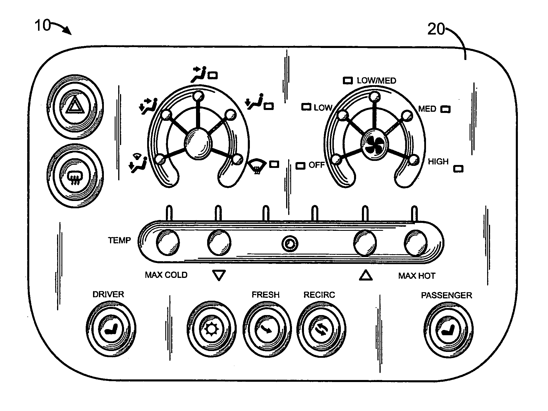
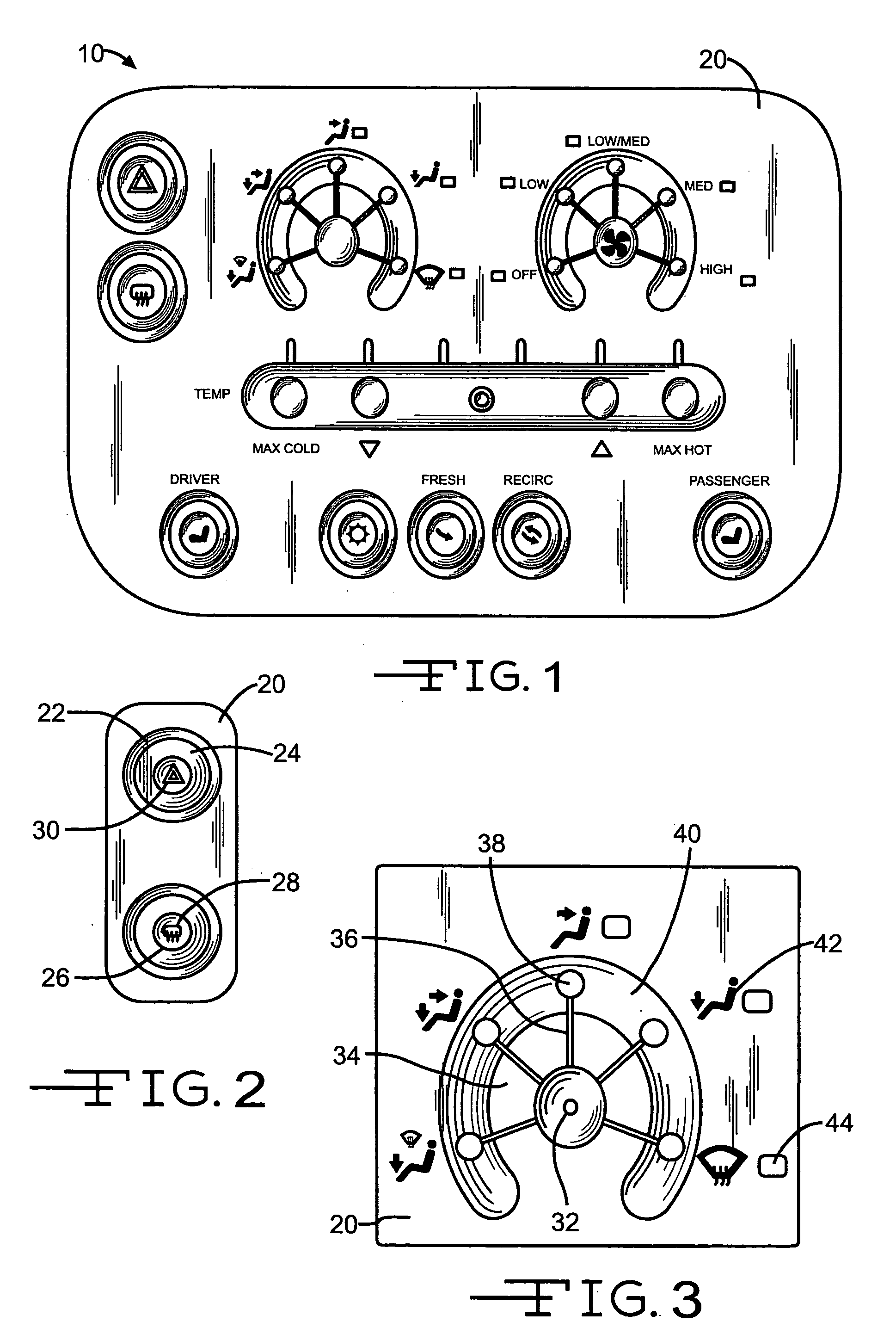
[0020]Referring now to the drawings, there is illustrated in FIG. 1 an interface in the form of a switch bank, generally indicate at 10, that is adapted to be integrated in the center stack of the motor vehicle. The switch bank 10 comprises a switch or switch array, which is a number of switches, that is operable to actuate and de-actuate one or more electrically operated devices (not shown) of the motor vehicle, such as the driver's and passenger's heated seats, hazard flashers, rear defogger, and climate control system of the motor vehicle.

[0021]The switch bank 10 is preferably made of a material, such as a plastic-based material, that is molded or otherwise crafted as desired to produce a substantially rigid structure having a desired style. The molding of motor vehicle interior trim components is well known to those of ordinary skill in the art of the invention and thus will not be described in further detail.

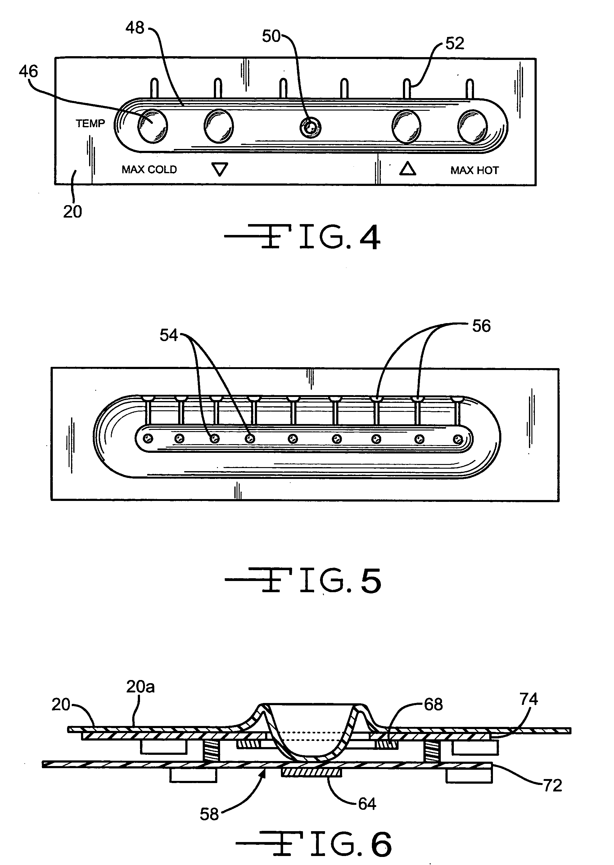
[0022]The switch bank 10 is preferably molded in a single piece, havin...


PUM


Abstract

An interface is in the form of a switch bank for the center stack of a motor vehicle. The switch bank comprises a motor vehicle interior trim component and at least one non-movable switch located behind the interior trim component. The switch is operable to actuate and de-actuate an electrically operated device of the motor vehicle.

Description

BACKGROUND OF INVENTION[0001]This invention relates in general to motor vehicles and more particularly to an interface for controlling operations of a motor vehicle. Most particularly, the invention relates to a center stack switch bank for motor vehicles.[0002]A conventional interface for a motor vehicle typically includes a switch bank, which generally comprises a large number of switches that are mounted in and around the armrests, console, and / or dashboard of the motor vehicle. Certain switch banks are typically located forward and between the driver and front passenger of the motor vehicle in an interior trim component that is commonly referred to as a “center stack”. The center stack generally contains switches for controlling the motor vehicle entertainment system and climate control functions. By filling the center stack with the sound system and climate control switches of the motor vehicle, the area ahead of the driver and front passenger is left bare.[0003]A conventional ...

Claims


Application Information

Patent Timeline
Patent Type & Authority Patents(United States)
IPC IPC(8): H01H9/00B60H1/00B60K37/06H03K17/96
CPCB60H1/00985H03K17/962B60K37/06H03K2217/960755B60K2350/1024H01H2215/03H01H2215/05H01H2217/018H01H2217/024H01H2219/03H01H2229/062H01H2231/026H01H2239/006H01H2239/01H01H2239/048H03K2217/96062B60K2370/143B60R16/02H03K17/955
Inventor HEIN, DAVID A.
Owner LEAR CORP
Why Eureka
Try Eureka