Light emitting apparatus, method for driving the light emitting apparatus, and display apparatus including the light emitting apparatus

a technology of light emitting apparatus and light emitting device, which is applied in the direction of electroluminescent light sources, static indicating devices, instruments, etc., can solve the problems of inability to control the desired emission intensity, inability to separate control the emission wavelength and emission power, etc., and achieve the effect of suppressing the variation of emission intensity and light color of the led devi

Inactive Publication Date: 2007-02-20
SHARP KK
View PDF7 Cites 96 Cited by
  • Summary
  • Abstract
  • Description
  • Claims
  • Application Information

AI Technical Summary

Benefits of technology

[0036]Thus, the invention described herein makes possible the advantages of providing (1) a method for driving an LED device having a light color which is blue shifted with a driving current value, in such a manner that the emission intensity of the LED device is changed while maintaining the light color of the LED device from being changed; (2) a method for driving an LED device in which variation of the emission intensity and light color of the LED device can be...

Problems solved by technology

Thus, a desired emission intensity control cannot be conducted.
It is not possible to separately control the emission wavelength and emi...

Method used


Image

  • Light emitting apparatus, method for driving the light emitting apparatus, and display apparatus including the light emitting apparatus
  • Light emitting apparatus, method for driving the light emitting apparatus, and display apparatus including the light emitting apparatus
  • Light emitting apparatus, method for driving the light emitting apparatus, and display apparatus including the light emitting apparatus

Examples


example 1

[0062]A light emitting apparatus according to Example 1 of the present invention includes: a light emitting section for emitting light in which a color of the light is blue shifted with a value of a driving current; and a driving section for driving the light emitting section so that the light emitting section emits light having a desired color and a desired intensity, by generating the driving current based on a signal designating the desired color and a signal designating the desired intensity and by applying the driving current to the light emitting section. In description of Example 1, the light emitting section serves as an LED device, and the driving section serves as an LED on-off circuit.

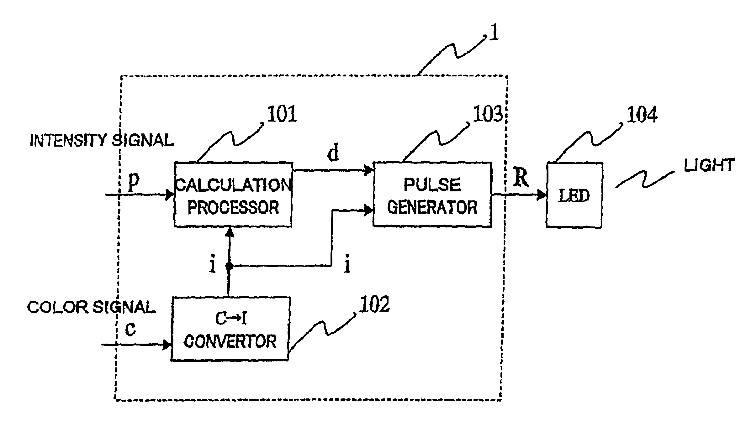
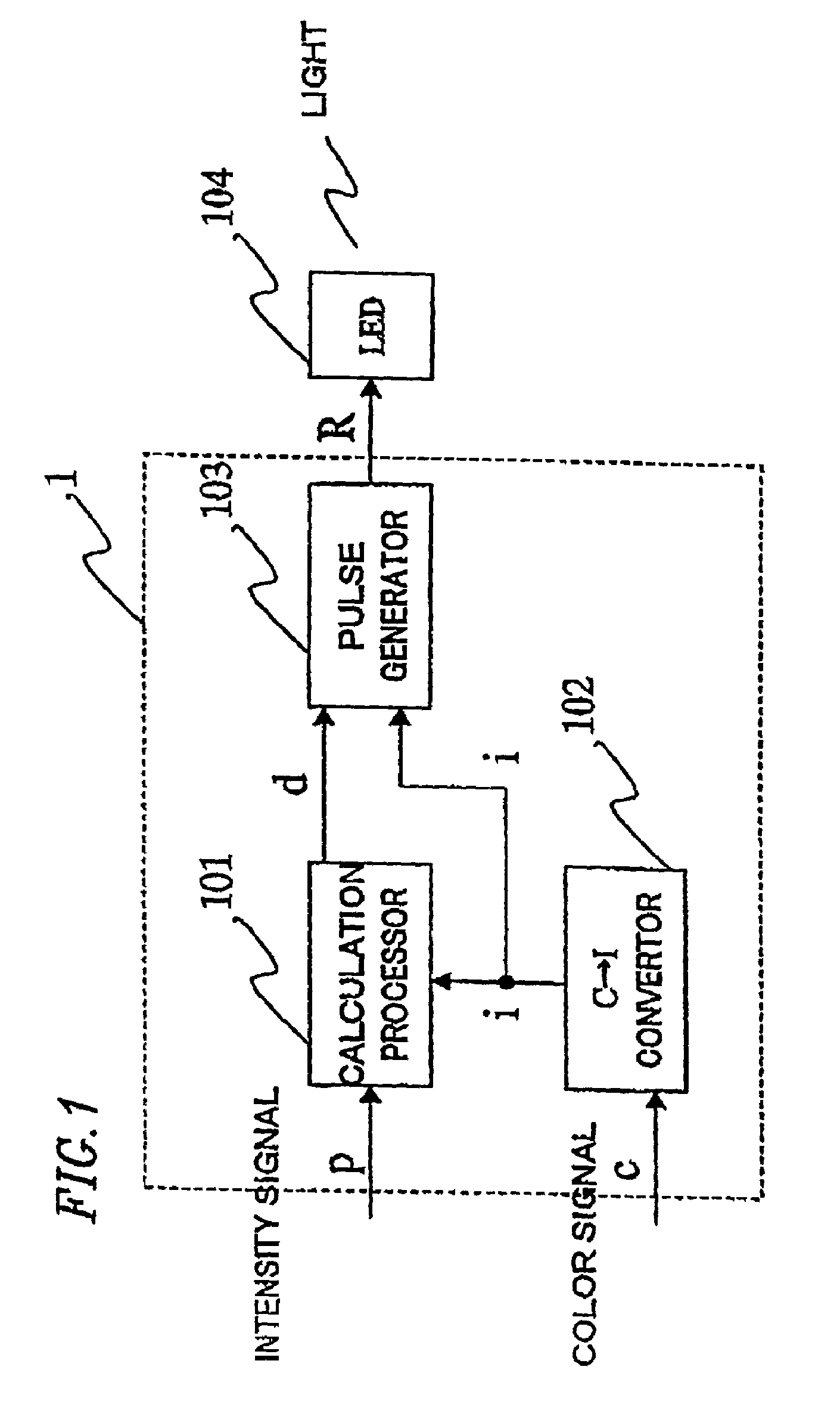
[0063]FIG. 1 illustrates an LED apparatus according to Example 1 of the present invention. The LED apparatus of Example 1 includes an LED on-off circuit 1 for outputting an LED driving current R based on an intensity signal p and a color signal c, and an LED device 104 having a light color w...

example 2

[0090]In Example 2, the LED apparatus (including DEVICE 1) of Example 1 is employed. An attempt is made, where the emission intensity of the LED device 104 is temporally changed from about 50 μW to about 100 μW to about 200 μW while the emission wavelength of the LED device 104 is maintained constant. In such an attempt, the color signal c is constantly equal to c490, and the intensity signal p is changed from p50 to p100 to p200.

[0091]Since the color signal c is constantly equal to c490, the color signal-current value signal converter 102 outputs the same current value signal i as that in Example 1, i.e., i=i2.

[0092]The duty signal d output from the calculation processor 101 is calculated in a procedure similar to that in Example 1. As the intensity signal p is changed from p50 to p100 to p200, the duty signals d (=d0.25, d0.5, and d1), which cause the duty D to be about 0.25, about 0.5, and about 1, respectively, are sequentially sent to the pulse generator 103.

[0093]Thus, in such...

example 3

[0096]In Example 3, a simplified variant of the LED on-off circuit of Example 1 is provided. Referring to FIG. 7, the LED on-off circuit of Example 3 is comprised of only a square wave pulse generator 103a. It is only the intensity signal p that is externally input to the LED on-off circuit. The square wave pulse generator 103a only modifies the duty of a current pulse which is to be supplied to the LED device 104 based on the value of the intensity signal p while maintaining the peak value of a current at a predetermined constant value. If a change in wavelength (blue shift) of the LED device 104 is controlled so that the range of change is about 6 nm or less, variation in the peak value of a current does not substantially cause problems. In this case, the peak value of a current is regarded as being constant. When the peak value of a current is set to the maximum of the range in which the reliability of the LED device 104 can be secured, the dynamic range of the emission intensity...


PUM


Abstract

A light emitting apparatus comprises a light emitting section for emitting light, a color of the light being changed with a value of a driving current, and a driving section for driving the light emitting section so that the light emitting section emits light having a desired color and a desired intensity, by generating the driving current based on a signal designating the desired color and a signal designating the desired intensity and by applying the driving current to the light emitting section.

Description

BACKGROUND OF THE INVENTION[0001]1. Field of the Invention[0002]The present invention relates to a light emitting apparatus and a method for driving the light emitting LED apparatus. The present invention also relates to a display apparatus including the light emitting apparatus.[0003]2. Description of the Related Art[0004]FIG. 20 illustrates a conventional LED driving apparatus. In the conventional LED driving apparatus, a driving current i corresponding to an output establishment value p is applied from a power source 191 to an LED device 192 to drive the LED device 192. The emission intensity of the LED device 192 is controlled by changing the value of the driving current i. In general, the color of light emitted from conventional LED devices does not depend on the value of a driving current. Thus, the emission intensity of conventional LED devices is changed by control of the driving current value while maintaining the color of light emitted from the LED devices.[0005]The emissi...

Claims


Application Information

Patent Timeline
IPC IPC(8): G09G3/32G09G3/20H01L33/06H01L33/32H01L33/40H01L33/50H05B44/00
CPCG09G3/14G09G3/2081G09G3/32H05B33/0866H05B33/0818H05B33/0821H05B33/086G09G3/2014G09G2310/0272G09G2320/0666G09G2330/021G09G2320/0626H01L2224/48091H01L2224/49107H05B45/24H05B45/20H01L2924/00014
Inventor KAMIKAWA, TAKESHIITO, SHIGETOSHITANEYA, MOTOTAKA
Owner SHARP KK
Why Eureka
Try Eureka