Deformable mirror, optical head, and optical recording and playback device

a technology of optical head and mirror, which is applied in the direction of data recording, instruments, mountings, etc., can solve the problems of deterioration of light spots, spherical aberration, and change in the thickness of light-transmitting layer, and achieves simple configuration, low cost, and simple configuration

Inactive Publication Date: 2007-05-03
PANASONIC CORP
View PDF3 Cites 12 Cited by
  • Summary
  • Abstract
  • Description
  • Claims
  • Application Information

AI Technical Summary

Benefits of technology

[0047] When configured in this manner, a deformable mirror that corrects spherical aberration using a simple configuration can be achieved, and compact, low-power optical head and optical recording and playback device can be also achieved.
[0048] According to the deformable mirror of the invention, a deformable mirror that corrects spherical aberration, caused by a difference in thickness of the light-transmitting layer in a dual layer disc, using a simple configuration at a low cost can be provided, and a compact optical head can be thereby achieved.
[0049] In addition, because it is configured in such a manner that a divergence angle of a parallel beam can be switched in the vicinity of the objective lens, a change in efficiency for utilization of a laser beam and in the rim intensity can be suppressed, which makes it easy to design the optical system.
[0050] Moreover, in order to correct spherical aberration, a current is passed through for a short time only when two layers are switched. Hence, power consumption needed for correction can be reduced to the minimum.
[0051] Hence, because power consumption is low, it is possible to achieve compact, low-power, and inexpensive optical head and optical recording and playback device that can be installed in a mobile device.

Problems solved by technology

Generally, spherical aberration occurs in collected light with a change in thickness of the light-transmitting layer and a light spot is deteriorated.
Spherical aberration occurring due to a difference in thickness of the light-transmitting layer is therefore no longer allowable.
These methods in the background art, however, have problems as follows.
Firstly, the configuration to deform the thin-film mirror increases the cost, because it is quite difficult to manufacture the mirror having a satisfactory flat surface in the initial state.
In addition, when a sufficiently high initial tensile force is provided to the thin-film mirror so that the flatness can be maintained regardless of a change in environmental temperature, an extremely large electrostatic force is necessary to deform the mirror, which requires the driving at a high voltage.
Hence, the power consumption is so large that this method is not suitable in a case where a quantity of correction for spherical aberration is changed between two recording layers.
Secondly, in the case of the configuration to move the collimator lens, the optical head cannot be reduced in size due to the need for the moving span for the lens, the guiding structure, and a space to dispose a driving actuator or the like on the optical path in the optical system.
This makes it difficult to design the optical system.

Method used


Image

  • Deformable mirror, optical head, and optical recording and playback device
  • Deformable mirror, optical head, and optical recording and playback device
  • Deformable mirror, optical head, and optical recording and playback device

Examples


first embodiment

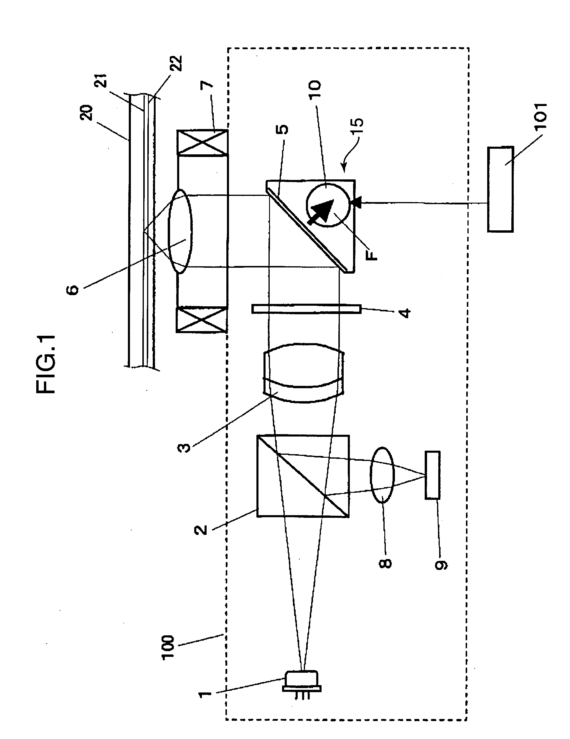
[0069]FIG. 1 is a schematic view showing the configuration of an optical head according to a first embodiment of the invention.

[0070] As is shown in FIG. 1, an optical head 100 includes a laser light source 1, a polarization beam splitter 2, a collimator lens 3, a quarter-wave plate 4, a deformable mirror 15 having a reflection mirror 5, an objective lens 6, a collective lens 8, and a photo-detector 9. The laser light source 1 emits a laser beam. The polarization beam splitter 2 transmits a laser beam that comes incident on one side while reflecting a laser beam that comes incident on the other side.

[0071] The quarter-wave plate 4 converts a polarization direction of light. The reflection mirror 5 deflects the optical axis direction. The objective lens 6 concentrates leaser beams on the information recording surface of a dual layer optical disc 20. The collective lens 8 collects reflected light from the dual layer optical disc 20 on a light-reception portion in the photo-detector ...

second embodiment

[0130] A second embodiment of the deformable mirror 15 of the invention will now be described concretely. Like components are labeled with like reference numerals with respect to the first embodiment, and descriptions of such components are omitted herein.

[0131]FIG. 10 is a perspective view showing the second embodiment of the deformable mirror 15 of the invention. FIG. 11 is a perspective view showing respective disassembled components. The reflection mirror 5, the base 11, and the elastic supporting member 12 are of the same configurations as their counterparts in the first embodiment.

[0132] As are shown in FIG. 10 and FIG. 11, the base 11 is provided with axial grooves 11b, and a movable portion 30 supported rotatably on the axial groove 11b is incorporated into the base 11.

[0133] The movable portion 30 includes a movable portion base 33, driving yokes 34, and driving magnets 35.

[0134] The movable portion base 33 is provided with a large rectangular concave portion 33b at the...

third embodiment

[0152] A third embodiment of the deformable mirror 15 of the invention will now be described. Like components are labeled with like reference numerals with respect to the first embodiment, and descriptions of these components are omitted herein.

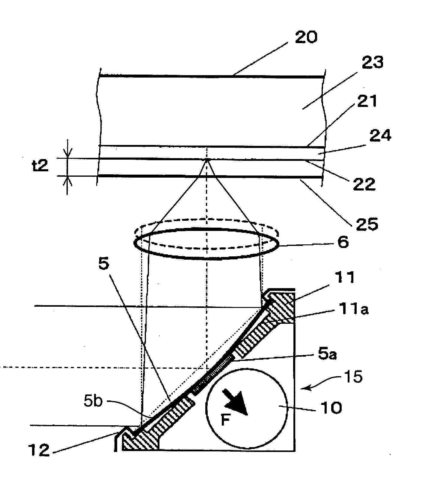
[0153]FIG. 15 is a cross section showing the third embodiment of the deformable mirror 15 of the invention. As is shown in the drawing, the magnetic member 5a is provided across the entire back surface of the base member 5b forming the reflection mirror 5, so that the attraction force is exerted across the entire surface. Meanwhile, the recessed portion 11a in the base 11 is formed in the shape of a concave curved surface that coincides with deformation of the reflection mirror 5.

[0154] When configured in this manner, the attraction area is enlarged in comparison with a case where the magnetic member 5a is provided at the center of the reflection mirror 5 alone. Hence, even when the provided gap flux density is the same, it is possible to o...


PUM

PropertyMeasurementUnit
thicknessaaaaaaaaaa
thicknessaaaaaaaaaa
thicknessaaaaaaaaaa

Abstract

For a recording and playback optical head used for a dual layer disc, it is difficult to reduce the size and the cost due to the need to correct spherical aberration caused by a difference in thickness of a light-transmitting layer. A reflection mirror having a reflection surface on which light is reflected and provided with a member having ferromagnetism at the center, and a switching device that switches between a deformed state and a non-deformed state of the reflection mirror using a magnetic force are provided. The switching device includes a hard magnetic member, and a magnetizing member that magnetizes and demagnetizes the hard magnetic member. When light is concentrated on a first recording layer farther from the light-incident surface, the reflection mirror is used as a plane mirror, and when light is concentrated on a second recording layer closer to the light-incident surface, the reflection mirror is deformed in the shape of a concave surface by means of the switching device.

Description

FIELD OF THE INVENTION [0001] The present invention relates to an optical head that records / plays back information in / from an optical recording and playback medium, and more particularly, to a deformable mirror for use in an optical head that corrects spherical aberration occurring with a change in thickness of a light-transmitting layer in an optical recording and playback medium having two recording layers, and an optical head and an optical recording and playback device using the same. DESCRIPTION OF THE RELATED ART [0002] Optical recording and playback media, such as a playback-only optical disc, a phase-change optical disc, and a magneto-optical disc, have been used extensively to save video information, sound information, computer data, or the like. The optical recording and playback media are now used as video recording media as an alternative to videotapes, and further as recoding media for high-density videos. The need for information recoding media to increase a recording ...

Claims


Application Information

Patent Timeline
Patent Type & Authority Applications(United States)
IPC IPC(8): G11B7/135G02B7/182G02B26/08G03B30/00
CPCG02B26/0825G11B7/1362
Inventor KUROZUKA, AKIRAMUSHIKA, YOSHIHIRO
Owner PANASONIC CORP
Why Eureka
Try Eureka