Check patentability & draft patents in minutes with Patsnap Eureka AI!

Intelligent data pool management engine

Active Publication Date: 2007-02-20
TAIWAN SEMICON MFG CO LTD
View PDF4 Cites 6 Cited by
  • Summary
  • Abstract
  • Description
  • Claims
  • Application Information

AI Technical Summary

Problems solved by technology

This architecture consumes many hardware and software resources.
When a client connects to one of the databases, the connection setup consumes a great deal of time.
This architecture still has disadvantages, because the executing job performance impacts the jobs waiting in the job queue.

Method used


Image

  • Intelligent data pool management engine
  • Intelligent data pool management engine
  • Intelligent data pool management engine

Examples


Embodiment Construction

[0013]The data pool models of the prior art used a predetermined, static number of channels, in spite of the variable volume of the connection traffic. Depending on the actual traffic conditions, an individual channel allocation may have been too high or too low at different times.

[0014]An exemplary embodiment of the present invention provides an efficient middle-tier application server as a management engine for multiple database connections. The exemplary embodiment operates a data pool for each backend database independently and dynamically analyzes each database's connection activity during a relevant period, for optimizing data channel pre-allocations, to reduce unnecessary consumption of resources.

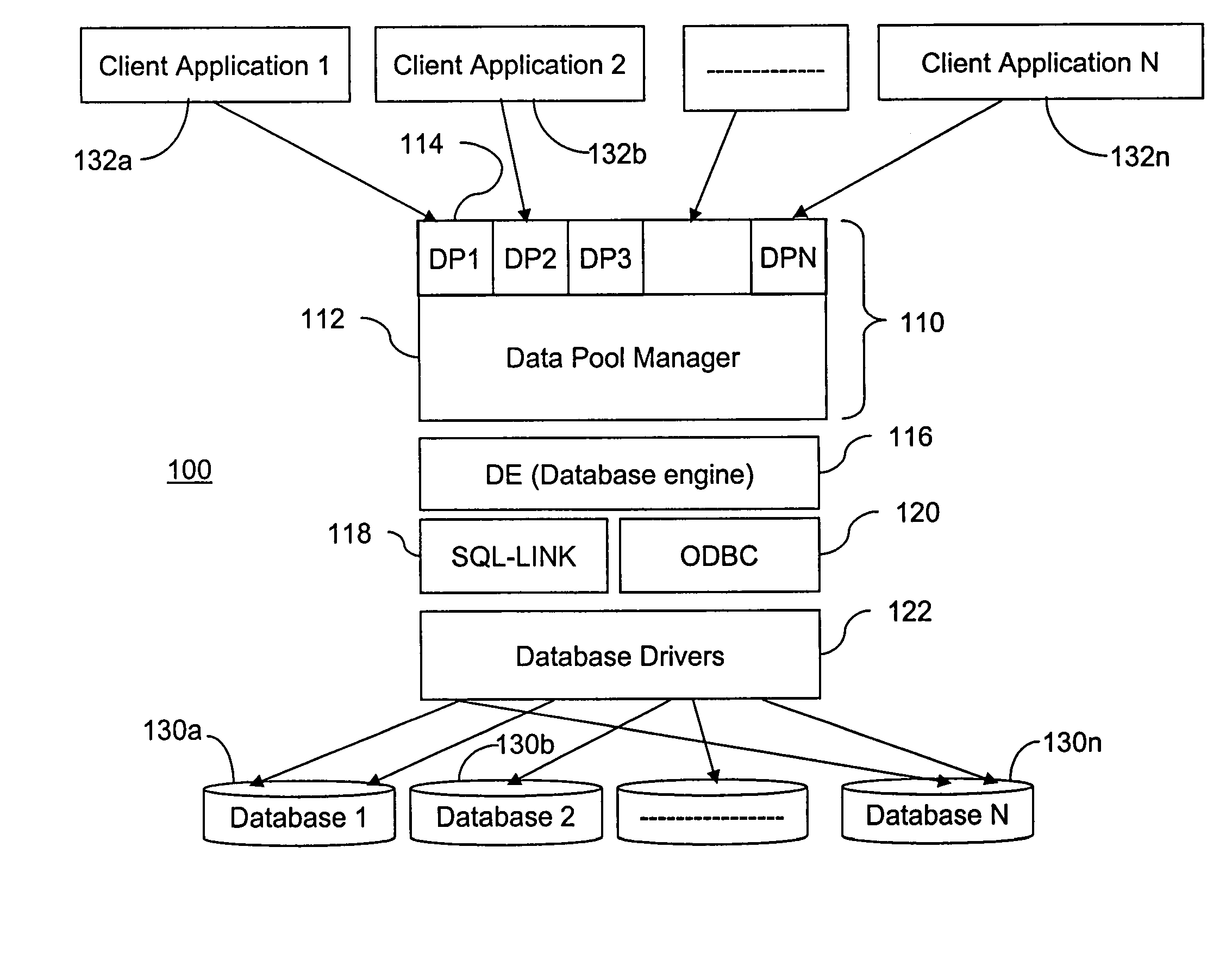
[0015]FIG. 1 is a block diagram of an exemplary system 100 including a data pool manager 110 according to one embodiment of the present invention. In system 100, a plurality of client applications 132a–132n access databases 130a–130n, where any of the clients can access any of the da...


PUM


Abstract

A method of managing access by a plurality of clients to a plurality of respectively different databases comprises the steps of: receiving a plurality of requests by the plurality of clients to access a plurality of different databases, the queries being received by a single application server; dynamically analyzing use of channel connections between the single application server and the plurality of databases; and dynamically allocating the channel connections between the single application server and each of the plurality of databases to service the plurality of queries based on the analyzing.

Description

FIELD OF THE INVENTION[0001]The present invention relates to software generally, and more specifically to database management systems employing the three-tier model.BACKGROUND[0002]In a traditional three-tier architecture, many clients can connect to the same application server to access a database. The components, drivers and database link setup are only required to be installed on the computer where application server exists. This reduces the number of computers for information technology staff to install and maintain. However, the traditional model for a multi-tier application server connecting to a plurality of databases is one-to-one. For each backend database, there is a corresponding one or more application servers. Each application server can has a respective channel. This architecture consumes many hardware and software resources. When a client connects to one of the databases, the connection setup consumes a great deal of time. Further, the operation model for this archite...

Claims


Application Information

Patent Timeline
IPC IPC(8): G06F15/16G06F17/30H04L29/06H04L29/08
CPCH04L67/1008G06F17/3056H04L67/1023H04L67/14H04L2029/06054H04L67/1002G06F16/252H04L67/10015H04L67/1001
Inventor LU, YING-LON
Owner TAIWAN SEMICON MFG CO LTD
Features
  • R&D
  • Intellectual Property
  • Life Sciences
  • Materials
  • Tech Scout
  • Unparalleled Data Quality
  • Higher Quality Content
  • 60% Fewer Hallucinations
Learn More