Method for placing a device in a selected mode of operation

a device and mode of operation technology, applied in the field of serial communication interfaces, can solve the problems of increasing power consumption, relatively low device throughput in full power-down mode etc., and achieve the effect of reducing device throughput, increasing power consumption, and fast device throughpu

Inactive Publication Date: 2007-02-20
ANALOG DEVICES INC
View PDF12 Cites 14 Cited by
  • Summary
  • Abstract
  • Description
  • Claims
  • Application Information

AI Technical Summary

Benefits of technology

[0011]Three modes of operation related to power consumption are provided. These are the Fully-Powered Mode, Partial Power-Down Mode, and Full Power-Down Mode. In the Fully-Powered Mode, all portions of the device are fully powered at all times, so this mode of operation yields fastest device throughput but increased power consumption.
[0012]In the Partial Power-Down Mode of operation, power is removed from most portions of the device except when a conversion has been initiated. The Partial Power-Down Mode requires an extra conversion cycle for the first conversion performed, so device throughput is reduced in return for reduced power consumption.

Problems solved by technology

In the Fully-Powered Mode, all portions of the device are fully powered at all times, so this mode of operation yields fastest device throughput but increased power consumption.
Device throughput is relatively low in Full Power-Down Mode, primarily because of the extended time periods required both to place the device in Full Power-Down and to “wake it up” again.

Method used


Image

  • Method for placing a device in a selected mode of operation
  • Method for placing a device in a selected mode of operation
  • Method for placing a device in a selected mode of operation

Examples


Embodiment Construction

[0049]In accordance with the present invention, a read-only serial interface is used to place an integrated circuit device in a selected operating mode. The present invention provides distinct advantages when compared to mode control methodologies known in the prior art.

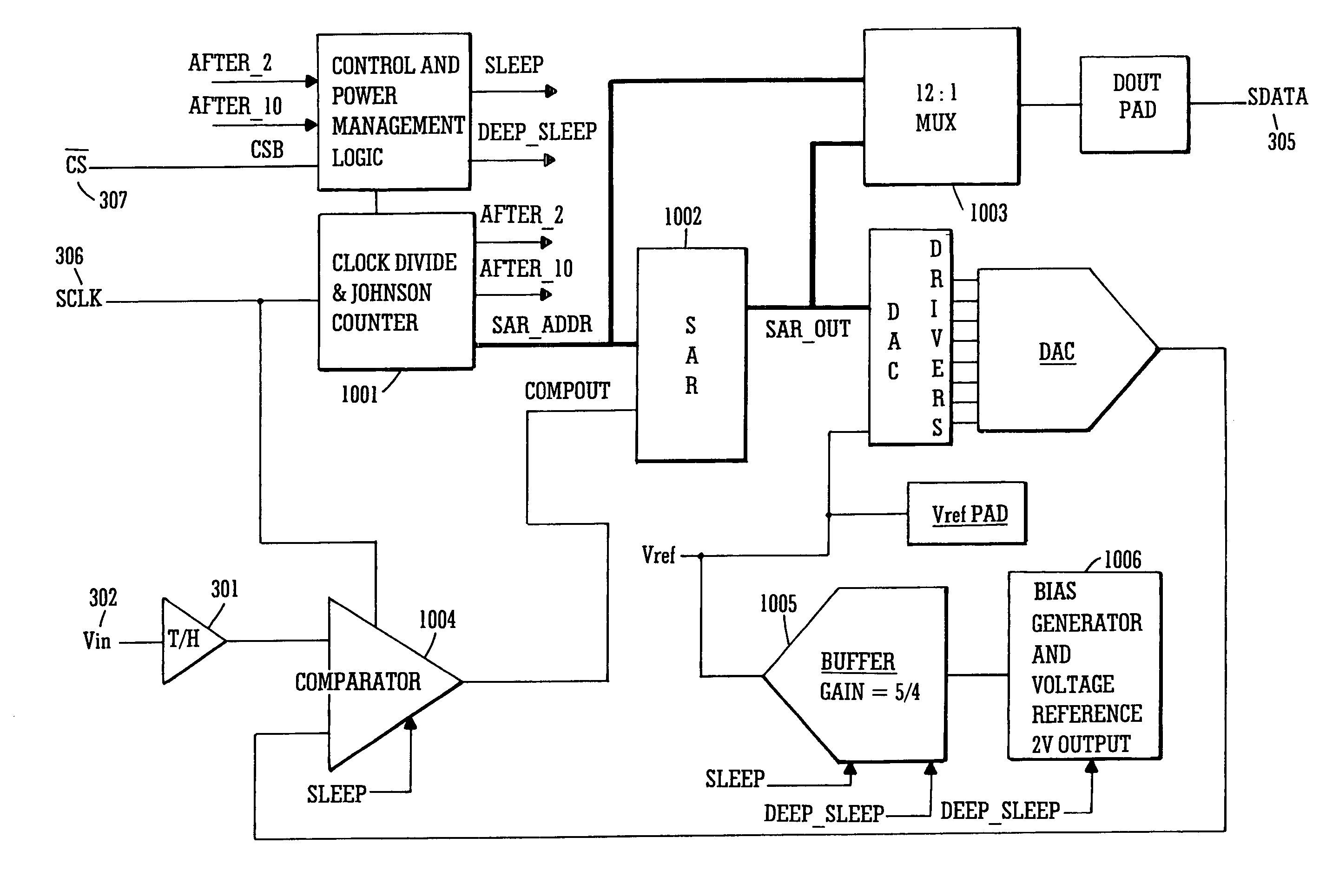
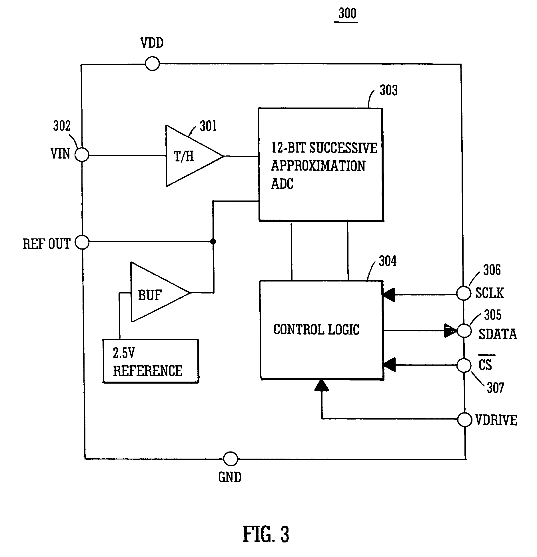
[0050]An example of an ADC integrated circuit having operational mode control in accordance with one form of the present invention is shown in simplified block diagram form in FIG. 3, and generally depicted by the numeral 300. The ADC 300 includes a track and hold circuit 301 for acquiring an analog input voltage 302. A 12-bit successive approximation register (SAR) ADC 303 converts the analog input signal 302 into a corresponding digital signal. The integrated circuit 300 includes control logic 304 that controls the operation of the other components of the integrated circuit 300, and also includes power control circuitry for selectively applying / removing power from portions of the device, although this power control...


PUM


Abstract

A method for placing a device in a selected mode of operation. The method comprises the steps of initializing a device select signal into a first logic state, asserting the device select signal in a second logic state, and returning the device select signal to the first logic state within a first user-controlled time window. A device is also described that includes means for detecting logic state transitions at a device select input and a clock input, and means for changing operating mode of the device in response to a predetermined number of logic state transitions at the clock input, occurring between logic state transitions at the device select input. The selected operating mode may be a reduced power consumption mode, for example, or another operating mode of the device, such as a daisy-chain mode of operation, or a mode that accommodates programming of analog input range.

Description

RELATED APPLICATIONS[0001]This application is a continuation-in-part of U.S. patent application Ser. No. 09 / 523,610, filed Mar. 13, 2000 now U.S. Pat. No. 6,681,332, and allowed on Aug. 21, 2003, entitled SYSTEM AND METHOD TO PLACE A DEVICE IN POWER DOWN MODES / STATES AND RESTORE BACK TO FIRST MODE / STATE WITHIN USER-CONTROLLED TIME WINDOW.FIELD OF THE INVENTION[0002]This invention relates generally to serial communication interfaces, and is more particularly directed toward utilizing a read-only serial interface to select an operating mode for a device.BACKGROUND OF THE INVENTION[0003]The popularity of battery-operated equipment, and the demand for smaller integrated circuit devices having lower power consumption (with consequent longer periods between battery replacement or recharging), has given rise to a need for reducing power consumption in the devices used in such equipment. One technique that has been developed involves supplying full power to a device during periods of so-cal...

Claims


Application Information

Patent Timeline
Patent Type & Authority Patents(United States)
IPC IPC(8): G06F1/26G06F1/32H03M1/00H03M1/12H03M1/42H03M1/46H03M1/70H04M1/73
CPCG06F1/3209H03M1/002H03M1/004H04W52/0287H03M1/462H03M1/70H03M1/46Y02D30/70
Inventor BYRNE, MICHAELO'BYRNE, NICOLAPRICE, COLINHUMMERSTON, DEREK
Owner ANALOG DEVICES INC
Why Eureka
Try Eureka