Molding device for producing thermoplastic containers

a thermoplastic container and molding device technology, applied in the field of molding devices, can solve the problems of increasing the weight of half-molds and also their cost, requiring each finger to be in solid form, and therefore heavy and costly, and achieves the effects of low angular amplitude, fast production throughput, and relatively rapid completion

Inactive Publication Date: 2008-06-10
SIDEL PARTICIPATIONS SAS
View PDF8 Cites 18 Cited by
  • Summary
  • Abstract
  • Description
  • Claims
  • Application Information

AI Technical Summary

Benefits of technology

[0010]There is therefore a constant demand for molds of simplified structure, which are less cumbersome, lighter, simpler and less expensive, this demand being made more acute by the desire for increased production throughput which requires devices which function more rapidly with low inertia.
[0019]Due to the arrangements of the invention, locking means for the two half-molds in the closed position are formed such that the forces separating these half-molds during certain steps (pre-blow molding, blow molding) are uniformly absorbed over the entire height of the mold. Moreover, the locking and unlocking processes of the mold obtained by rotating a rotatable gib about one of its edges are obtained by relatively small angles of rotation of the gib, for example in the order of 20°: such a rotation of relatively low angular amplitude may be carried out relatively rapidly. This rapidity of the locking and unlocking processes is completely incorporated within the scope of the functioning constraints desired by users of equipment for producing thermoplastic containers by blow molding or stretch blow molding, for which even faster production throughput is required. Moreover, emphasis is given to the structural simplicity of the locking means proposed according to the invention which comprise only a single mobile part which is, naturally, high (i.e. the height of the mold), but of low thickness and relatively narrow width. As a result, the gib has relatively low inertia during rotation which, in turn, moves in a direction allowing increased throughput. Finally, designing the half-molds for the structural and functional layout of the gib does not require substantial additions of material, such that the inertia of the mobile half-molds is also substantially reduced relative to the previous solutions. Generally, the assembly of locking means designed according to the invention allows a significant increase to be considered in the functioning speed of the mold during the closing / locking and unlocking / opening phases, at the same time that the weight of the peripheral elements (pins, supports, etc.) may also be reduced.

Problems solved by technology

Nevertheless, these locking means have several significant drawbacks.
One drawback is that the fingers and receiving apertures are supported in a cantilevered manner by the first and second half-molds, respectively.
To avoid deformation or tearing thereof, it is necessary for these supports to be in solid form, which increases the weight of the half-molds and also their cost.
A further drawback is in the cantilevered structure of each finger, of which the base is fitted into a radially projecting support attached to a half-mold whilst, in the locked position, the free end of the finger is retained in a corresponding receiving aperture of a radially projecting support attached to the other half-mold.
Under the influence of the blowing force, each finger is subjected to bending / shear stress which, in turn, requires each finger to be in solid form and therefore heavy and costly.
All these requirements lead to the locking means substantially projecting over the periphery of the mold, whilst in equipment comprising a large number of molds and functioning at high speed (rotational molding devices of the carousel type), the available space is very limited.
Moreover, these locking means are heavy and increase the inertia of the half-molds, which is detrimental for equipment which functions with fast throughput.
This eventually results in a non uniform distribution of the forces over the height of the mold.

Method used


Image

  • Molding device for producing thermoplastic containers
  • Molding device for producing thermoplastic containers
  • Molding device for producing thermoplastic containers

Examples


Embodiment Construction

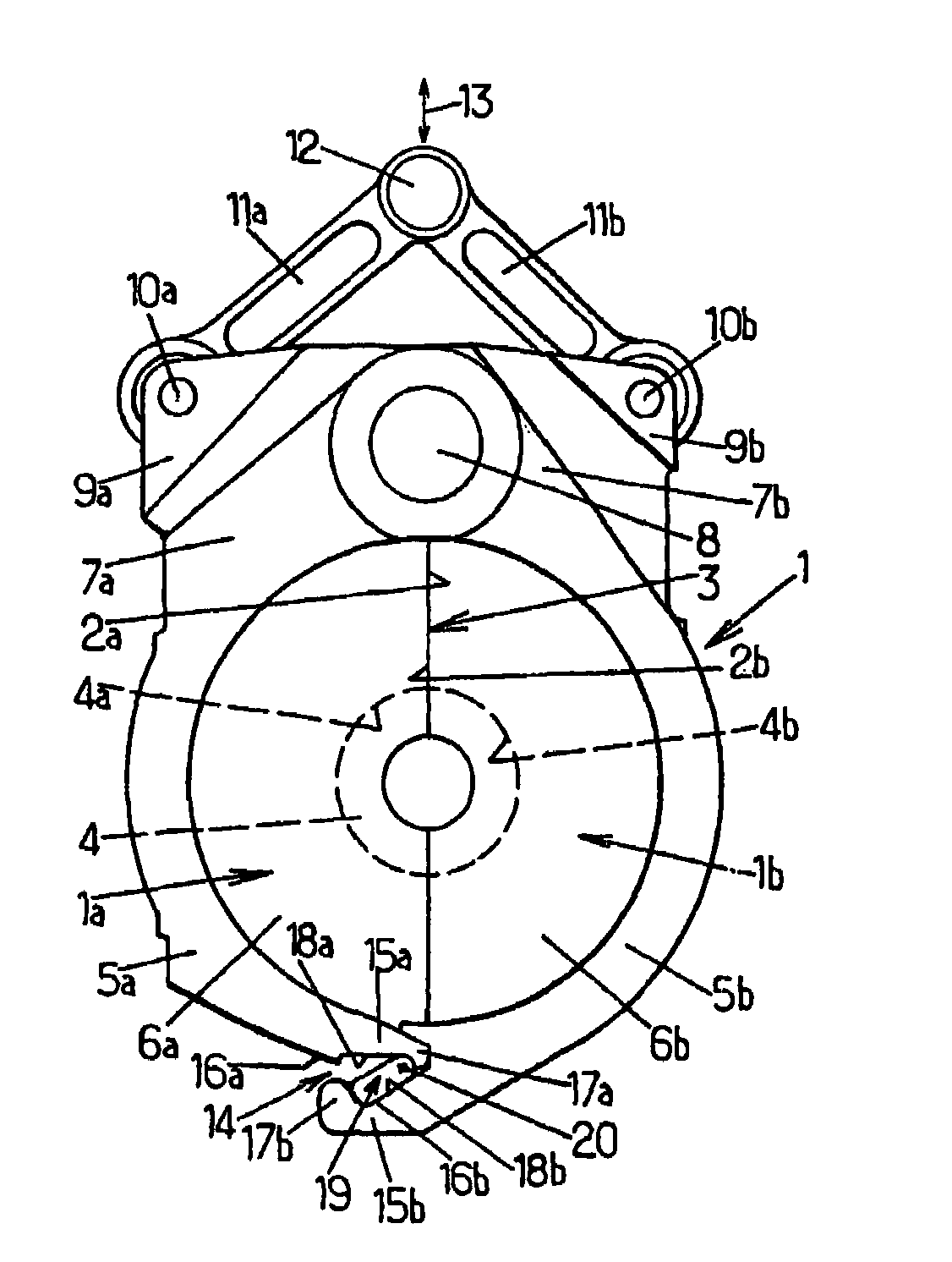
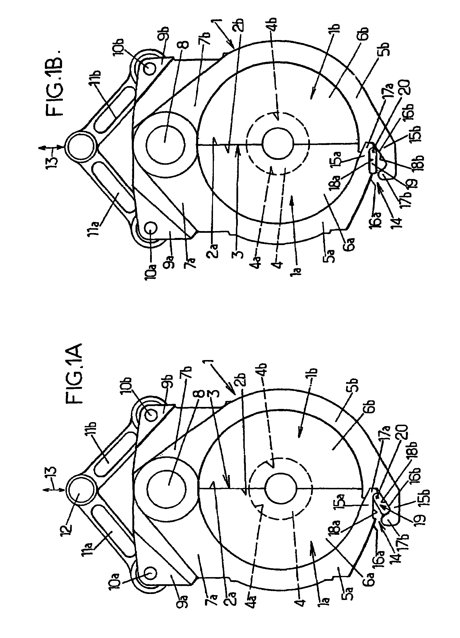
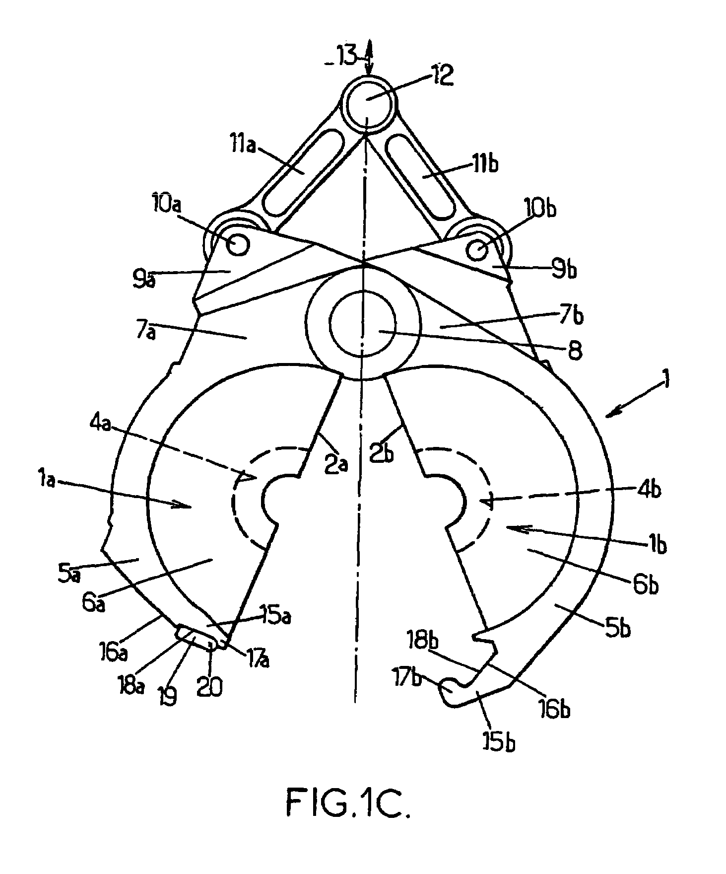
[0031]The arrangements according to the invention are improvements made to the molding devices for producing containers, such as bottles, by blow molding or stretch blow molding, from preforms made of a heated thermoplastic (for example PET). Such a molding device comprises at least one mold consisting of at least two half-molds (possibly a third part forms an axially displaceable mold base) which are mutually displaceable between an open position in which they are separated from one another and a closed position in which they are tightly pressed against one another by respective mating faces defining a joint plane, locking means being provided to lock the two half-molds in the closed position and to prevent their separation or partial opening when the blow molding fluid is introduced under very high pressure (for example typically in the order of 40×105 Pa).

[0032]Currently, such molding devices may comprise a plurality of molds and may therefore be designed in the form of a rotatin...


PUM

PropertyMeasurementUnit
pressureaaaaaaaaaa
heightaaaaaaaaaa
forcesaaaaaaaaaa

Abstract

A molding device for blow molding recipients made of a thermoplastic material, including a mold having two mold halves which are movable with respect to each other and provided with a locking device extending along the total height of the mold halves and including two respective hooks, which are oriented toward each other, two respective recesses adjacent to the hooks and a rotatable gib adjacent to the hook and interacting with the other hook in such a way that the two mold-halves are locked in the closed position thereof or are released from each other, the gib being inserted into the recess.

Description

FIELD OF THE INVENTION[0001]The present invention generally relates to the field of molding devices for producing containers by blow molding or stretch blow molding from preforms made of a heated thermoplastic.[0002]More particularly, the invention relates to improvements made to those devices comprising at least one mold consisting of at least two half-molds, mutually displaceable between an open position in which they are separated from one another and a closed position in which they are tightly pressed against one another by respective mating bearing faces defining a parting line, the two half-molds having at least two respective corresponding edges of their respective bearing faces which are designed in the form of two mutually overlapping edges with radially opposing respective mating faces, in the closed position of the mold, locking means being functionally associated with said overlapping edges.DESCRIPTION OF THE PRIOR ART[0003]Locking means for two half-molds in the closed ...

Claims


Application Information

Patent Timeline
Patent Type & Authority Patents(United States)
IPC IPC(8): B29C49/00B29C49/56B29C33/26B29C49/06B29C49/36
CPCB29C49/56B29C33/26B29C49/06B29C49/36B29C2791/001B29K2067/00B29C2049/023B29C2049/5661B29C2049/5662B29C2949/0715B29C33/20B29C49/28
Inventor MIE, PATRICKLEMAISTRE, ERICROUSSEAULANGLOIS, PIERRE-FRANCOIS
Owner SIDEL PARTICIPATIONS SAS
Why Eureka
Try Eureka