
Beveled insert for facilitating coupling pipes

Active Publication Date: 2007-02-27
INFRA TECT INC
View PDF15 Cites 6 Cited by
  • Summary
  • Abstract
  • Description
  • Claims
  • Application Information

AI Technical Summary

Benefits of technology

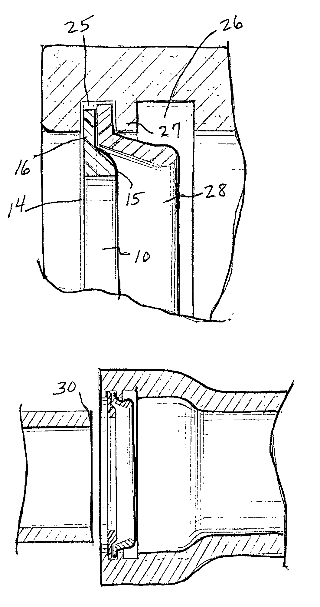
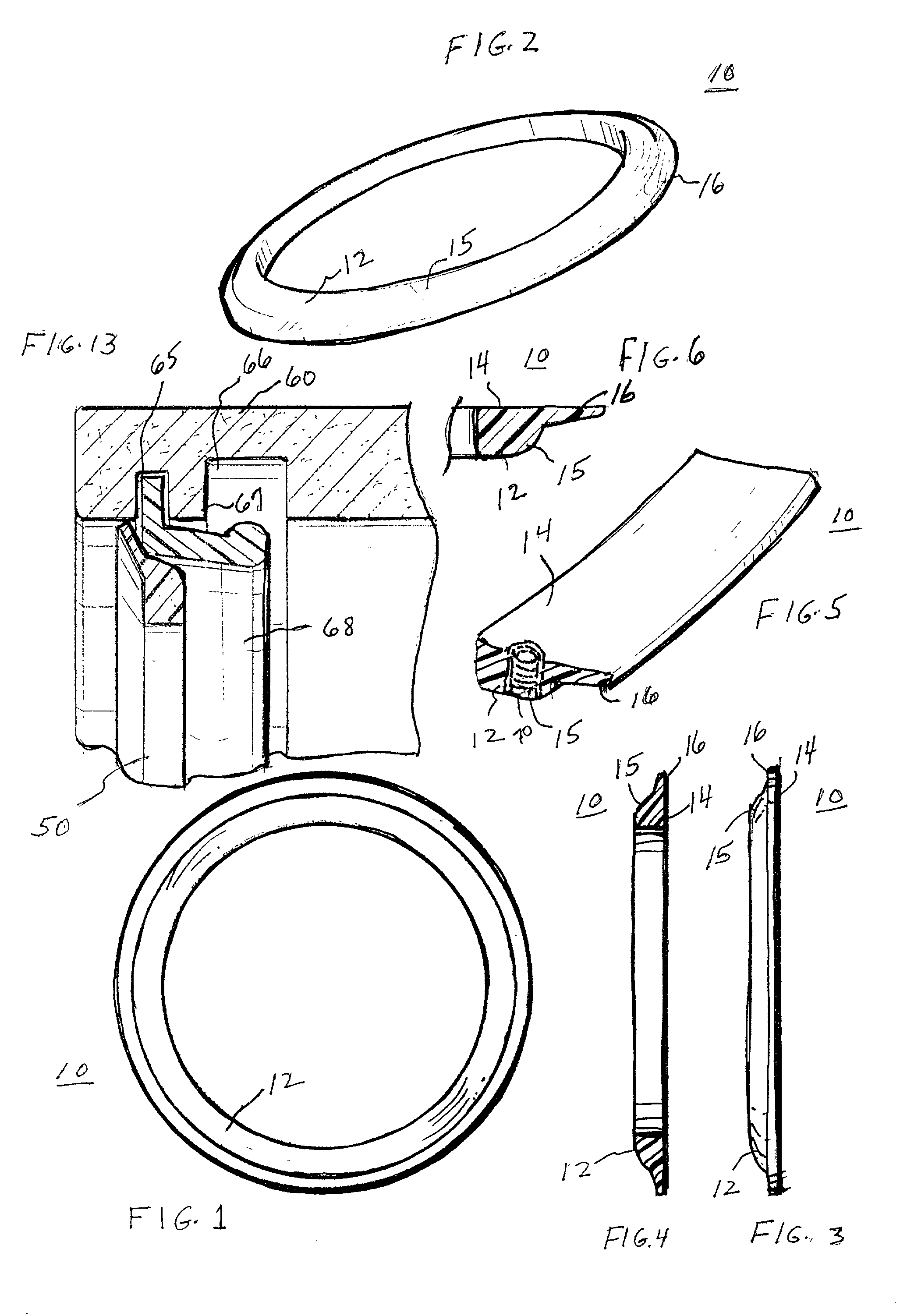
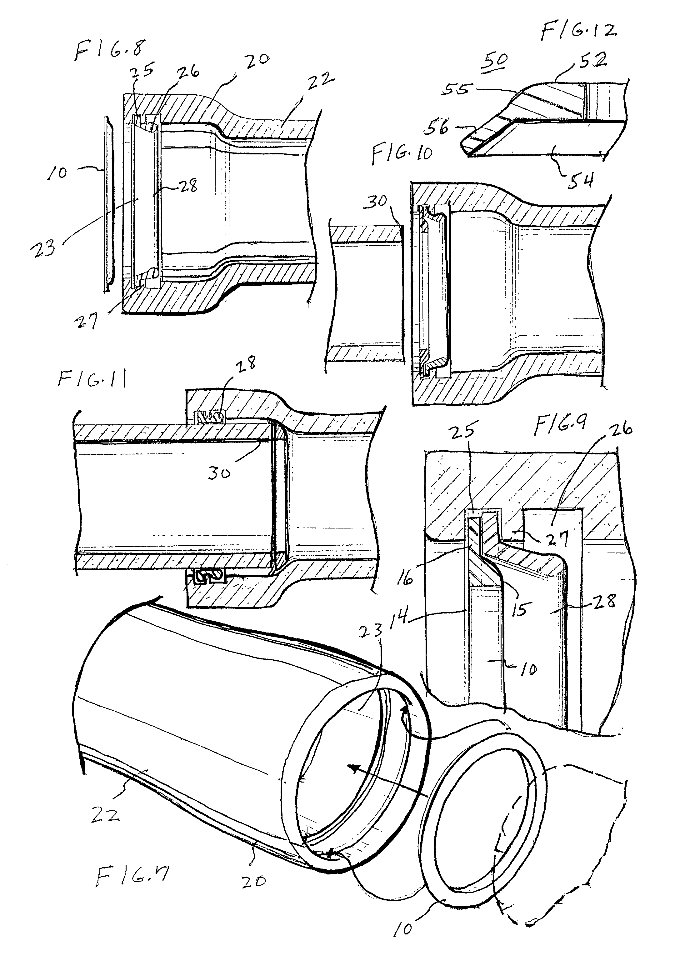
[0012]Briefly, to achieve the desired objects of the instant invention in accordance with a preferred embodiment thereof, provided is an annular beveled insert for enhancing the insertion of a plain end of a pipe into a mating belled end of a pipe. The insert includes an annular main body portion having a substantially flat surface and a beveled opposed surface. The annular main body portion has inner and outer diameters approximately equal to inner and outer diameters, respectively, of the plain end of the pipe. An outwardly directed flange extends from the annular main body portion around a periphery and has an outer diameter greater than the outer diameter of the plain end of the pipe. The flange engages an inner surface of the belled end to temporarily hold the beveled insert in place as the plain end is inserted into the belled end. The flange is sufficiently flexible so that it bends into an angle of approximately ninety degrees with the flat surface of the annular main body portion and aids the main body portion in masking the plain end of the pipe as it passes through the annular gasket.

Problems solved by technology

However, problems develop when a length of pipe must be shortened by cutting.
The cut end of the pipe has a relatively sharp edge which when inserted into the belled end of the adjacent pipe may damage the gasket located therein.
This is typically referred to as “fish mouthing”, and results in leakage at the joint.
This, however, creates more problems.
Specifically, forming a bevel in ductile iron pipe is extremely difficult.
The saw used is cumbersome and heavy, has a blade turning at approximately 5600 rpms, and is therefore dangerous and imprecise.
Furthermore, the blade manufacturers specifically prohibit this use of the blade, because the stresses are uneven and shattering of the blade tends to occur.
As well as being dangerous, forming a bevel in this manner is expensive due to the time in labor and increased number of blades used.
When done properly, beveled attachments work extremely well, but, as with many things, improperly positioned attachments may work improperly.

Method used


Image

  • Beveled insert for facilitating coupling pipes
  • Beveled insert for facilitating coupling pipes
  • Beveled insert for facilitating coupling pipes

Examples


Embodiment Construction

[0028]Typically, water mains employ a type of pipe known as ductile iron. Lengths of pipe are coupled by inserting the end of one pipe into a belled end of an adjacent pipe. Many times during this procedure, a pipe segment having a belled end receives a cut end of a pipe segment. The belled end is of conventional manufacture and includes an annular gasket carried therein. It should be pointed out that the term “belled” is used here to describe any pipe end that acts as a female fitting and is configured to receive another pipe end, and is intended to include pipes having at least a portion with a larger diameter than the inserted pipe. When a non-uniform length of pipe is required, a portion of a pipe segment must be removed by cutting, resulting in the cut end. Conventionally, when inserting the cut end into the belled end, damage will occur to the annular gasket. To prevent damage to the annular gasket by the cut end, often referred to as “fish mouthing”, a beveled attachment may ...


PUM


Abstract

An annular beveled insert for enhancing the insertion of a plain end of a pipe into a mating belled end of a pipe, the insert including an annular main body portion having a substantially flat surface and a beveled opposed surface. The annular main body portion has inner and outer diameters approximately equal to inner and outer diameters, respectively, of the plain end of the pipe. An outwardly directed flange extends from the annular main body portion around a periphery and has an outer diameter greater than the outer diameter of the plain end of the pipe. The flange is sufficiently flexible so that it bends into an angle of approximately ninety degrees with the flat surface of the annular main body portion and aids the main body portion in masking the plain end of the pipe as it passes through the annular gasket.

Description

FIELD OF THE INVENTION[0001]This invention relates to construction materials.[0002]More particularly, the present invention relates to pipe couplings.[0003]In a further and more specific aspect, the instant invention concerns devices for facilitating the coupling of pipes.BACKGROUND OF THE INVENTION[0004]Pipes have long been used for the delivery of various fluids, and the methods used for their installation are well-established. While the following invention can apply to many types of pipe for the delivery of many types of fluid, the following discussion will be focused upon liquid delivery, namely water pipes. Typically, water mains employ a type of pipe known as ductile iron. Lengths of pipe are coupled by inserting the end of one pipe into a belled end of an adjacent pipe. Using uncut lengths of pipe, this system works quite efficiently. However, problems develop when a length of pipe must be shortened by cutting. The cut end of the pipe has a relatively sharp edge which when in...

Claims


Application Information

Patent Timeline
IPC IPC(8): F16L17/00F16L21/03
CPCF16L21/03
Inventor WOLFF, STEVEN K.
Owner INFRA TECT INC
Learn More