Flexible circuit

Inactive Publication Date: 2007-06-28
UKA HARSHAD K
View PDF61 Cites 30 Cited by
  • Summary
  • Abstract
  • Description
  • Claims
  • Application Information

AI Technical Summary

Benefits of technology

[0017] In an aspect of the flexible circuit, a base layer fabricated from liquid crystal polymers are weak mechanically. Fortunately, flowing adhesive (e.g., liquid crys

Problems solved by technology

Secondly, an adhesive film is deposited over the continuous non reinforced flexible film.
Unfortunately, adhesives that bond well to the base film does not bond well to copper (i.e., conductive pattern), and conversely, adhesives that bond well to copper (i.e., conductive pattern) does not bond well to the base film.
Another problem with prior art flexible circuits relate to plated through holes.
Unfortunately, the conductive material that bonds well to adhesive does not bond well with the base film.
This failure typically results from z axis expansion and is referred to as plated through hole (PTH) failure.
Another problem with prior art flexible circuits relate to pin holes in base films which can potentially short circuit electrical circuits formed on the base films.
Further

Method used


Image

  • Flexible circuit
  • Flexible circuit
  • Flexible circuit

Examples


Embodiment Construction

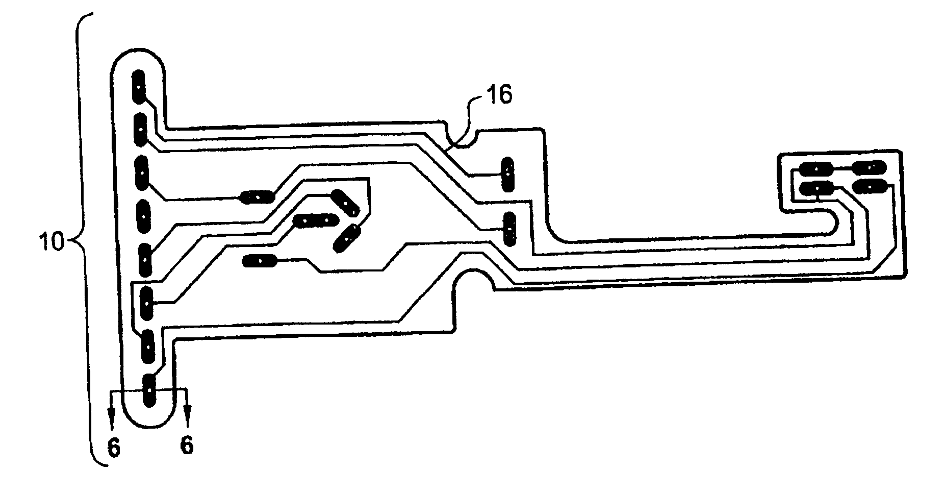
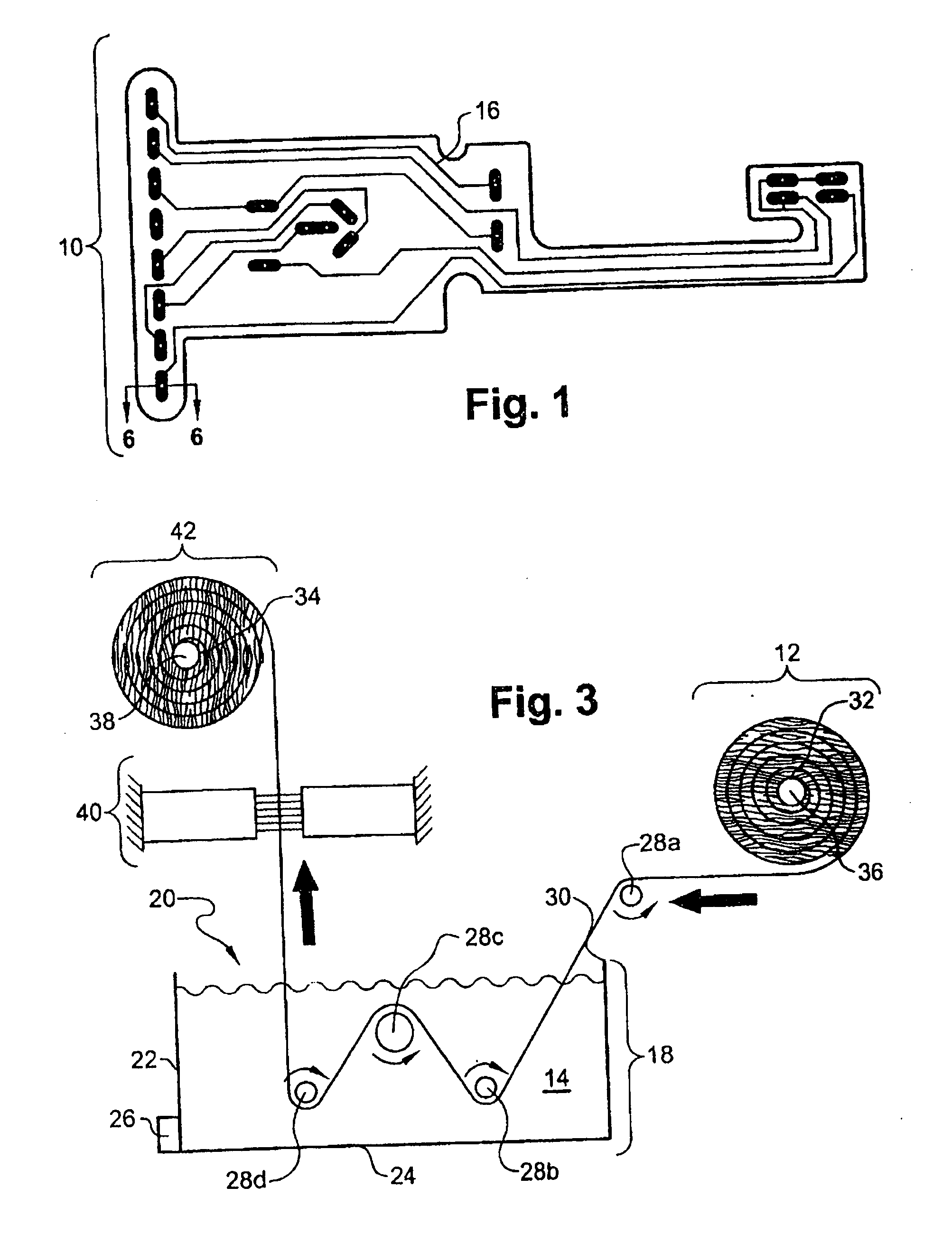
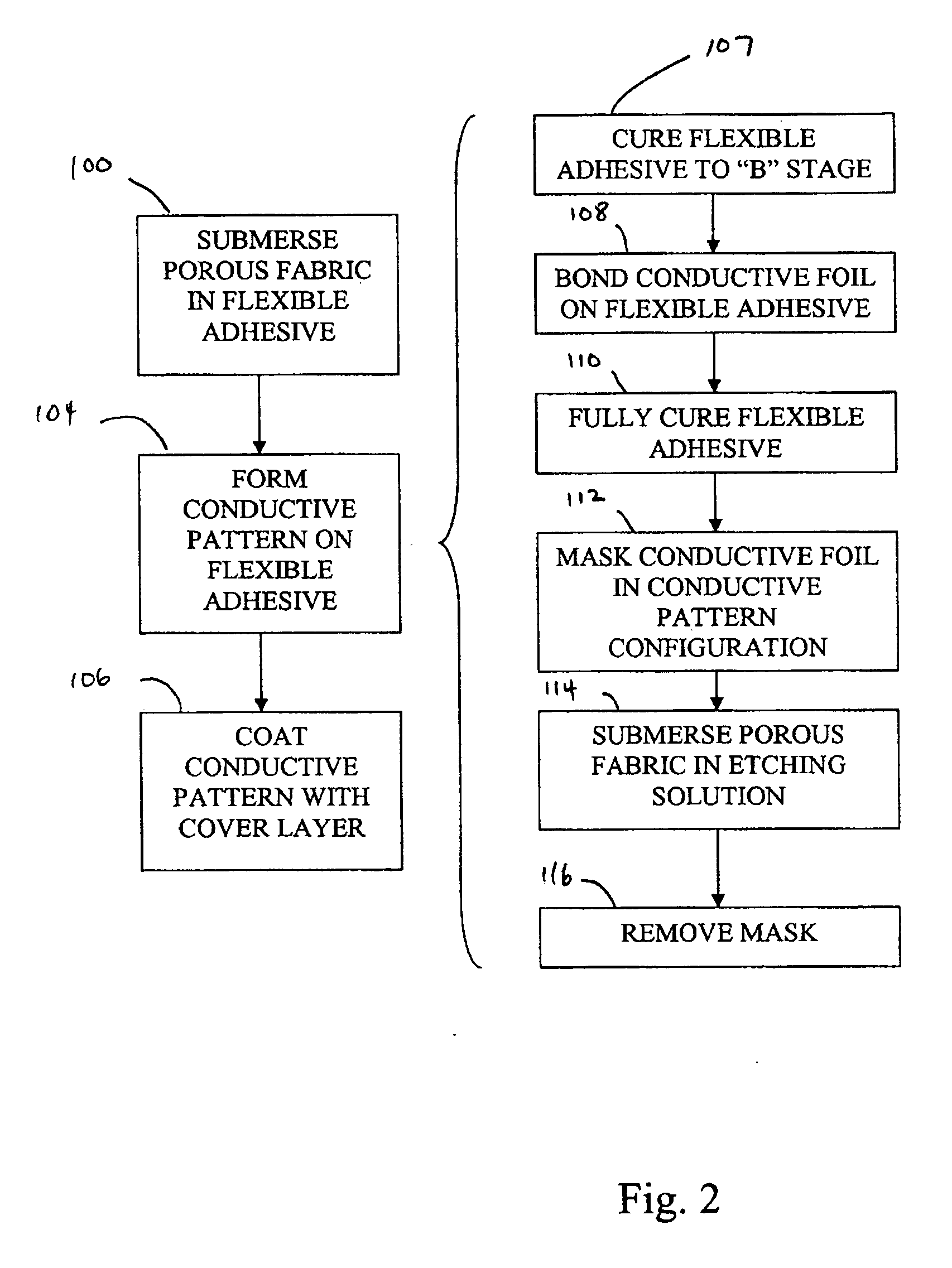
[0031] Referring now to FIGS. 1-3, a flexible circuit 10 is shown fabricated by submersing (step 100) a fabric 12 in an adhesive 14, forming (step 104) a conductive pattern 16 on the adhesive 14 of one side of the fabric 12, and coating (step 106) the conductive pattern 16 with a cover layer to protect the conductive pattern 16. The step of submersing 100 the fabric 12 in the adhesive 14 permits the adhesive 14 to flow through the fabric's interstices such that bending or flexing the flexible circuit 10 and / or the application of thermal stresses does not delaminate the adhesive 14 from the fabric 12. This step is different from the prior art process discussed in relation to FIG. 2A. In FIG. 2A, the adhesive is adhered to the exterior surface of the base film, whereas, the adhesive 14 discussed in relation to the present invention is disposed between the interstices of the fabric 12. Additionally, the adhesive 14 may be effectively formulated so as to adhere to the conductive pattern...


PUM

PropertyMeasurementUnit
Temperatureaaaaaaaaaa
Flexibilityaaaaaaaaaa
Electrical conductoraaaaaaaaaa

Abstract

A flexible circuit and a method of fabricating the flexible circuit is provided wherein adhesive is flowed into the interstices of a fabric. The adhesive is then cured to a “B” stage and a conductive foil is bonded to the adhesive on one or both sides of the fabric. Thereafter, the adhesive may be fully cured. A conductive pattern may then be etched into the conductive foil via print and etch techniques. The conductive pattern may be protected with a cover layer. For example, the cover layer may be a base layer with adhesive flowed in its pores and fully cured. The adhesive may be effectively formulated to withstand stresses between the adhesive and the conductive pattern such that bending and flexing the flexible circuit or subjecting the flexible circuit to thermal stresses does not delaminate the bond between the adhesive and the conductive pattern. The adhesive resists delamination from the fabric because the adhesive has been flowed into the fabric's interstices and cured.

Description

CROSS-REFERENCE TO RELATED APPLICATIONS [0001] Not Applicable STATEMENT RE: FEDERALLY SPONSORED RESEARCH / DEVELOPMENT [0002] Not Applicable BACKGROUND [0003] The present invention relates to flexible circuits. [0004] Flexible circuits are utilized in many different applications. A common application is in printed wiring harnesses and the like. For example, a printer may have first and second components electrically connected to each other which are required to have freedom of movement with respect to each other. The components may be electrically connected to each other via the printed wiring harness or interconnect. In particular, the flexible circuit may have a first set of conductive pads at a first distal end of the flexible circuit. The first set of conductive pads may be electrically connected to the first component. Also, the flexible circuit may have a second set of conductive pads at a second distal end thereof which are electrically connected to the second component and the...

Claims


Application Information

Patent Timeline
IPC IPC(8): H05K1/00H01B13/00C23F1/00C23C26/00H05K3/00B05D5/12
CPCC23C26/00C23C28/00H05K1/0366H05K1/0393H05K3/002H05K3/0055H05K3/181H05K3/386H05K3/387H05K3/388H05K2201/0116H05K2201/029H05K2201/0293
Inventor UKA, HARSHAD K.
Owner UKA HARSHAD K
Why Eureka
Try Eureka