Unlock instant, AI-driven research and patent intelligence for your innovation.

Zipper strip and method of positioning the strip transverse longitudinal axis

a technology of longitudinal axis and zipper strip, which is applied in the direction of sacks, packaging, flexible containers, etc., can solve the problems of high occurrence of leakage of packages, difficulty in achieving satisfactory sealing of bags or packages, and consistent and successful achievemen

Inactive Publication Date: 2007-02-27
ILLINOIS TOOL WORKS INC
View PDF22 Cites 8 Cited by
  • Summary
  • Abstract
  • Description
  • Claims
  • Application Information

AI Technical Summary

Benefits of technology

[0016]The tube is then sealed transversely to each length of zipper strip without the webs of the male and female interlocking profiles being sealed to each other. The tube is then cut transversely adjacent to each

Problems solved by technology

The indicated art is fairly well-developed, but nevertheless remains susceptible to improvement contributing to increased efficiency and cost effectiveness.
One problem that still hampers the production of packages from continuous zipper-equipped sheet material is the difficulty in attaining a satisfactory sealing of the bag or package against leakage, where the zipper and area of film engaged by the zipper extends through the side (cross) seal areas separating one bag or package from the next.
This problem occurs where the zipper is longitudinal with respect to the direction of motion of the thermoplastic sheet material used to form the reclosable bags on the FFS machine, in which case the transverse, or side, sealing bars must flatten and seal the zipper at the same time as they are sealing the thermoplastic sheet material from which the packages are being made.
The difficulty with which this is consistently and successfully achieved is reflected by the high occurrence of leaking packages.

Method used


Image

  • Zipper strip and method of positioning the strip transverse longitudinal axis
  • Zipper strip and method of positioning the strip transverse longitudinal axis
  • Zipper strip and method of positioning the strip transverse longitudinal axis

Examples


first embodiment

[0027]Referring specifically to the figures identified above, FIG. 1 is a cross-sectional view of the zipper strip 10 of the present invention. The zipper strip 10 comprises a male interlocking profile 12 and a female interlocking profile 14. The male interlocking profile 12 includes a male interlocking member 16 which may have an arrowhead-shaped cross section or, as is shown in FIG. 1, an asymmetrical arrowhead-shaped cross section, designed to make the zipper strip 10 easier to open from one side than from the other. The female interlocking profile 14 includes a female interlocking member 18 comprising two inwardly curving members forming a receptacle or channel into which male interlocking member 16 may be snappingly engaged.

[0028]Both the male and female interlocking profiles 12, 14 include webs coextruded with the male and female interlocking members 16, 18. Web 20 of male interlocking profile 12, it may be observed, is wider than web 22 of female interlocking profile 14. As a...

second embodiment

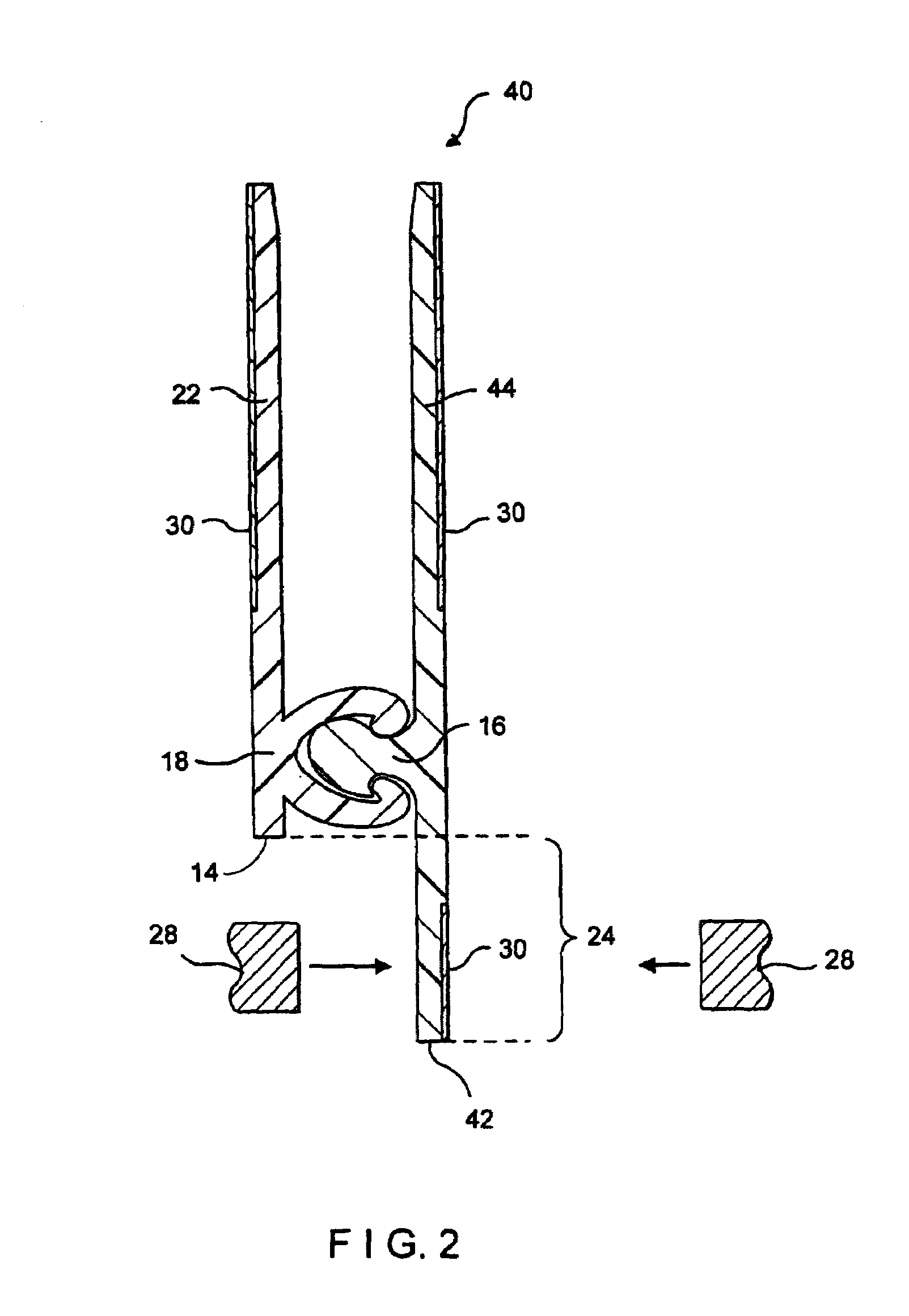
[0032]FIG. 2 is a cross-sectional view of the zipper strip 40 of the present invention. Elements common to both zipper strip 40 and zipper strip 10 described above are identified in FIG. 2 using the same reference numbers. A comparison between FIGS. 1 and 2 indicates that zipper strip 40 lacks a trailing flange 26, but is identical to zipper strip 10 in all other respects. As was the case with zipper strip 10, zipper strip 40 is disposed transversely across thermoplastic sheet material during the manufacture of plastic bags or packages on an FFS machine. Male interlocking profile 42 rests upon the thermoplastic sheet material. Heat seal bars 28 or the like, applied against the leading flange 24, as suggested by the arrows in FIG. 2, seal the male interlocking profile 42 to the thermoplastic sheet material (not shown) without sealing web 22 of the female interlocking profile 14 to web 44 of the male interlocking profile 42. As before, while the male interlocking profile 42 is shown t...


PUM


Abstract

A zipper strip for a reclosable bag or package includes a male interlocking profile and a female interlocking profile. The male interlocking profile includes a male interlocking member and a male web coextruded therewith. In like manner, the female interlocking profile includes a female interlocking member and a female web. The male interlocking member snappingly engages into the female interlocking member to join the profiles to one another. One of the male and female webs is wider than the other in at least one of two directions from the male and female interlocking members, the greater width being represented by at least one flange extending widthwise beyond the other web. The zipper strip is designed to be attached to thermoplastic sheet material by sealing the at least one flange thereto without sealing the male and female webs to each other. Methods for securing the zipper strip to thermoplastic sheet material, and for making packages on a horizontal form-fill-and-seal machine, are also disclosed.

Description

CROSS REFERENCE TO RELATED APPLICATIONS[0001]This application is a divisional of U.S. patent application Ser. No. 09 / 074,567 filed on May 7, 1998, now U.S. Pat. No. 6,044,621, which is a division of U.S. patent application Ser. No. 08 / 839,974 filed on Apr. 24, 1997, now abandoned, which application is a continuation-in-part (CIP) of U.S. patent application Ser. No. 08 / 651,977 filed on May 21, 1996.BACKGROUND OF THE INVENTION[0002]1. Field of the Invention[0003]The present invention relates to reclosable plastic bags of the type in which perishable food products and other goods are packaged for sale to consumers in retail outlets. More specifically, the present invention relates to reclosable plastic bags manufactured and concurrently filled on horizontal or vertical form-fill-and-seal (FFS) machines, wherein a plastic interlocking zipper for each bag is disposed transversely relative to the direction of motion of the thermoplastic sheet material used to form the reclosable bags on t...

Claims


Application Information

Patent Timeline
IPC IPC(8): B65D33/16
CPCB65D33/2533B65D33/2508B31B2219/9016B31B2219/9022B31B70/8131B31B70/8133
Inventor MALIN, ARTVAN ERDEN, DONALD L.KOHL, JR., JAMES G.MCMAHON, MICHAEL J.
Owner ILLINOIS TOOL WORKS INC