
Acoustic floor mat

Inactive Publication Date: 2007-02-27
PRETTY PROD
View PDF25 Cites 45 Cited by
  • Summary
  • Abstract
  • Description
  • Claims
  • Application Information

AI Technical Summary

Benefits of technology

[0004]Accordingly, it is an aspect of the present invention to

Problems solved by technology

Conventional floor mats, which absorb acoustic waves in a non-selective manner, can actually diminish the automobile design by undermining the desired sound management system.

Method used


Image

  • Acoustic floor mat
  • Acoustic floor mat
  • Acoustic floor mat

Examples


Embodiment Construction

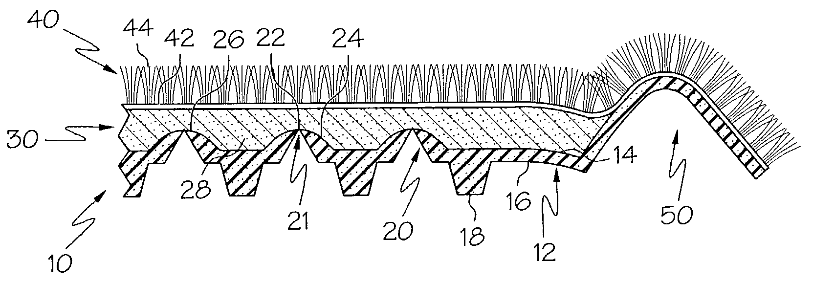
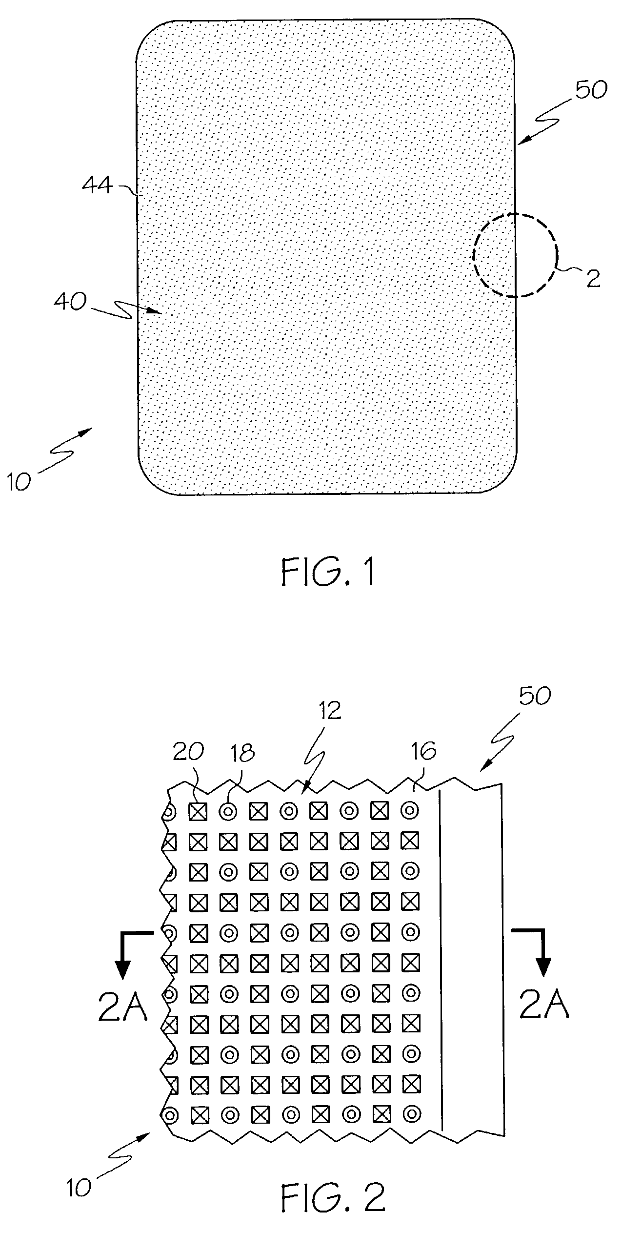
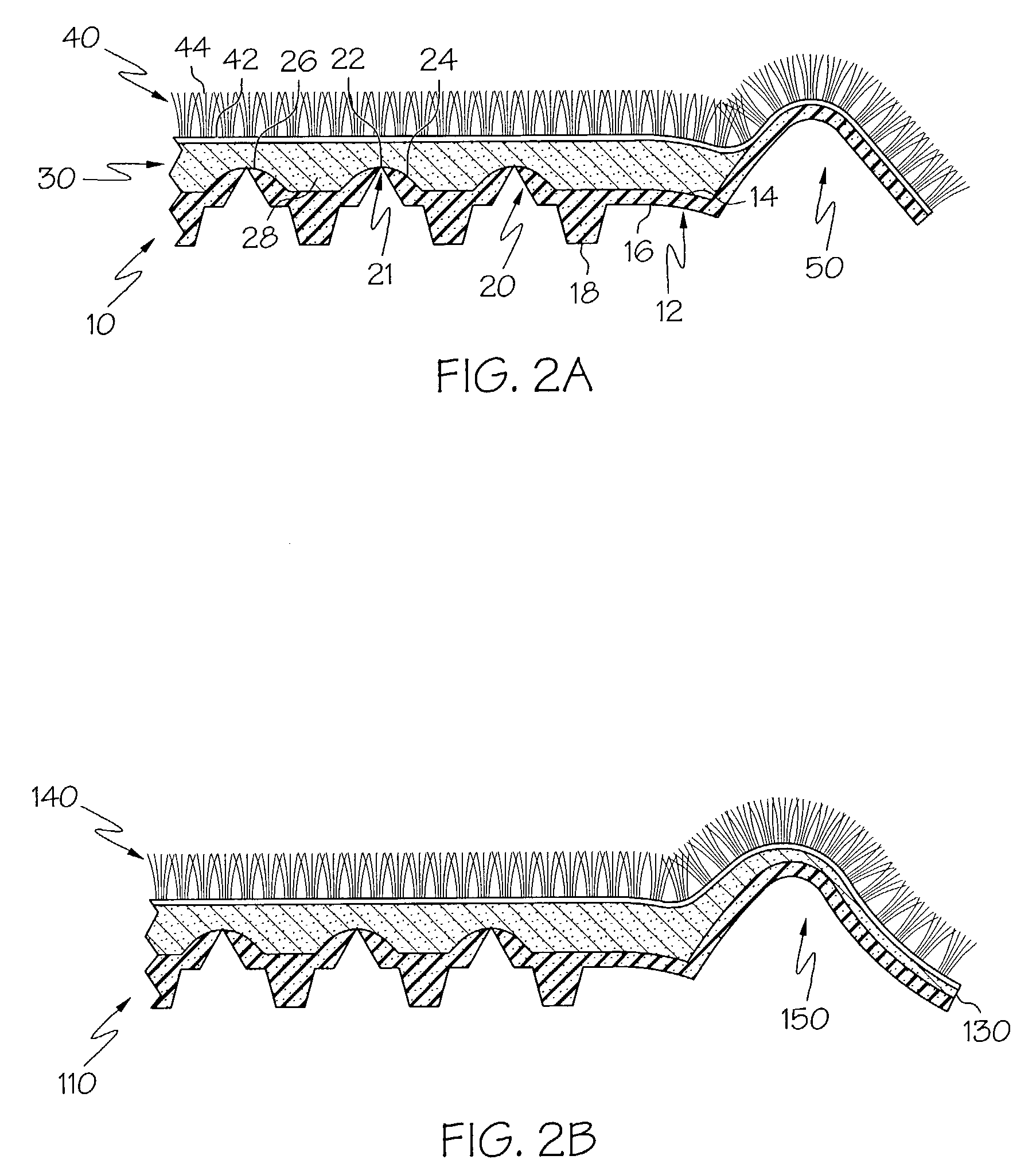
[0018]Turning now to the drawings in detail, wherein like numbers indicate the same or corresponding elements throughout the views, FIG. 1 depicts a top plan view of an acoustic floor mat 10 in accordance with one embodiment of the present invention. The upper surface of the floor mat includes a face layer 40. For example, as shown in FIG. 1, the face layer 40 of exemplary embodiments comprises a carpet material with a plurality of tufts extending away from a backing 42 to provide piles 44. If provided, the face layer of exemplary embodiments herein can also comprise any durable material that permits acoustic transmission therethrough. For example, the face layer can comprise a needle punch material (e.g., needle punch carpet, needle punch felt or the like), woven fabric, porous material or the like. While a substantially continuous and substantially uniform face layer is illustrated in the various exemplary embodiments, other non-continuous and / or non-uniform face layers may be emp...


PUM


Abstract

An acoustic floor mat is provided with a base layer, an upper surface, a lower surface, and a plurality of apertures configured to allow passage of acoustic transmissions therethrough. The base layer is further configured to provide a substantial barrier to the passage of liquid from the upper surface to the lower surface. Methods of making an acoustic floor mat are also disclosed.

Description

TECHNICAL FIELD[0001]This invention relates generally to acoustic material, and more particularly, to an acoustic floor mat configured to allow passage of acoustic transmissions therethrough while being configured to provide a substantial barrier to the passage of liquid.BACKGROUND OF THE INVENTION[0002]Floor mats are currently implemented by the industry for a variety of useful applications. For example, floor mats are commonly placed over the floorboard of an automobile adjacent the driver and passenger seats to protect the floorboard and / or automobile carpeting from wear, liquid and / or debris.[0003]Automobiles are also typically designed with structures in the floorboard for controlling unwanted noises while optimizing desirable sound such as on-board entertainment, safety features and the like. Conventional floor mats, which absorb acoustic waves in a non-selective manner, can actually diminish the automobile design by undermining the desired sound management system. Consequentl...

Claims


Application Information

Patent Timeline
IPC IPC(8): B32B3/10
CPCB32B3/30B60R13/083Y10T428/24521Y10T428/24496Y10T428/24479Y10T428/24273Y10T428/249981Y10T428/249976
Inventor SCOTT, COOKSEY TIMOTHY
Owner PRETTY PROD
Learn More