
Equipment service vehicle with remote monitoring

a technology for remote monitoring and equipment, applied in the direction of electric devices, anti-theft devices, process and machine control, etc., can solve the problems of increasing complexity and difficulty in maintaining modern vehicles, vehicle may be out of service for an extended period of time, and operators may be busy with other duties

Inactive Publication Date: 2007-02-27
OSHKOSH CORPORATION
View PDF216 Cites 313 Cited by
  • Summary
  • Abstract
  • Description
  • Claims
  • Application Information

AI Technical Summary

Problems solved by technology

Modern vehicles have become increasingly complex and difficult to maintain.
When a malfunction is not properly diagnosed, the result is typically that parts which are fully operational are repaired or replaced, that parts which are repairable are replaced, and / or that parts which are not fully operational are not repaired or replaced.
However, once a vehicle problem is diagnosed, there remains the potential that the vehicle may be out of service for an extended period of time.
However, operators may be busy with other duties and forget to schedule the equipment service vehicle for maintenance.
However, these methods may not reach those owners that purchased the vehicle used or have moved to a new location since the original sale.
Decreasing the amount of time spent on service and repair of the vehicle decreases the costs associated with maintaining and owning the vehicle.

Method used


Image

  • Equipment service vehicle with remote monitoring
  • Equipment service vehicle with remote monitoring
  • Equipment service vehicle with remote monitoring

Examples


Embodiment Construction

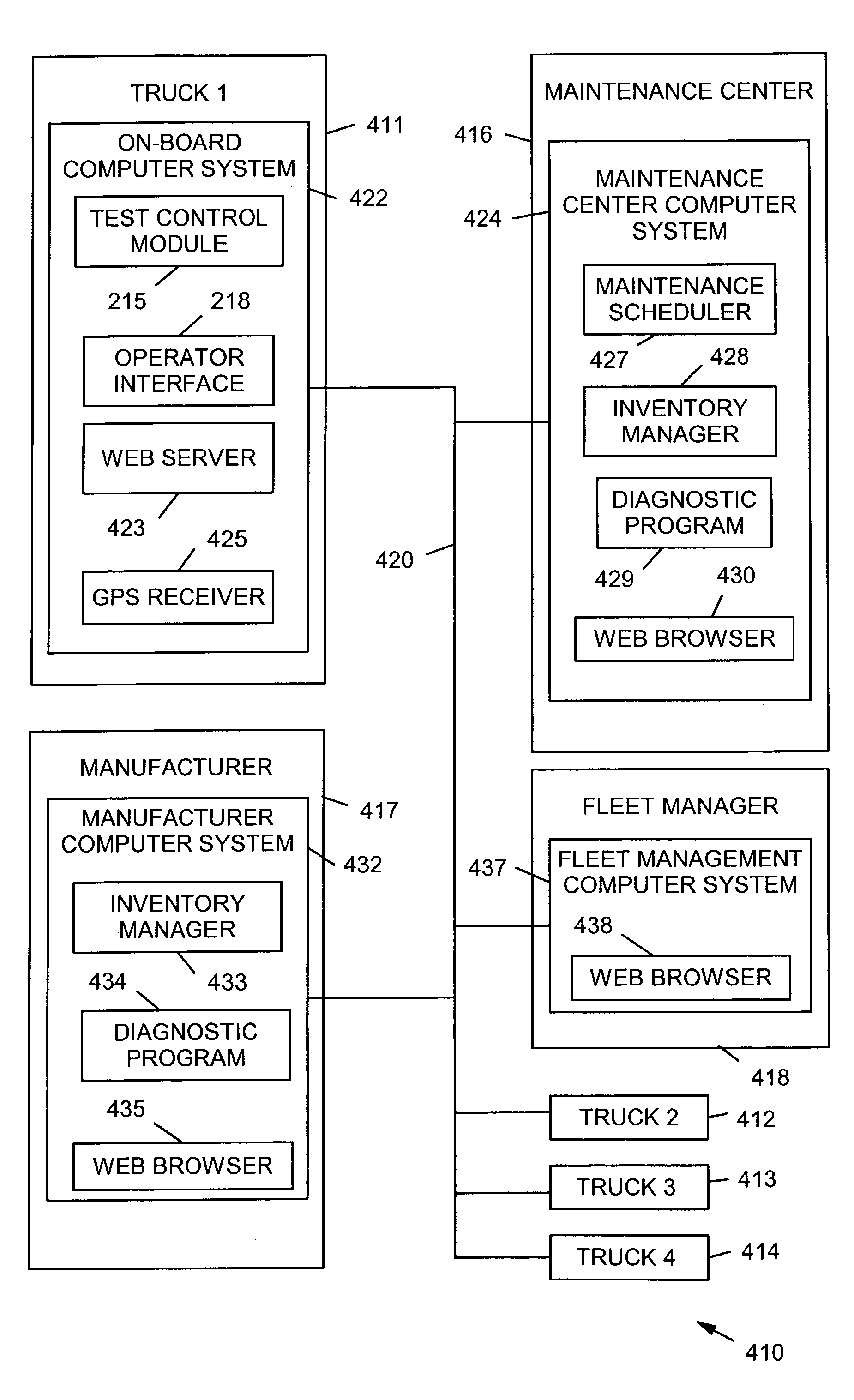
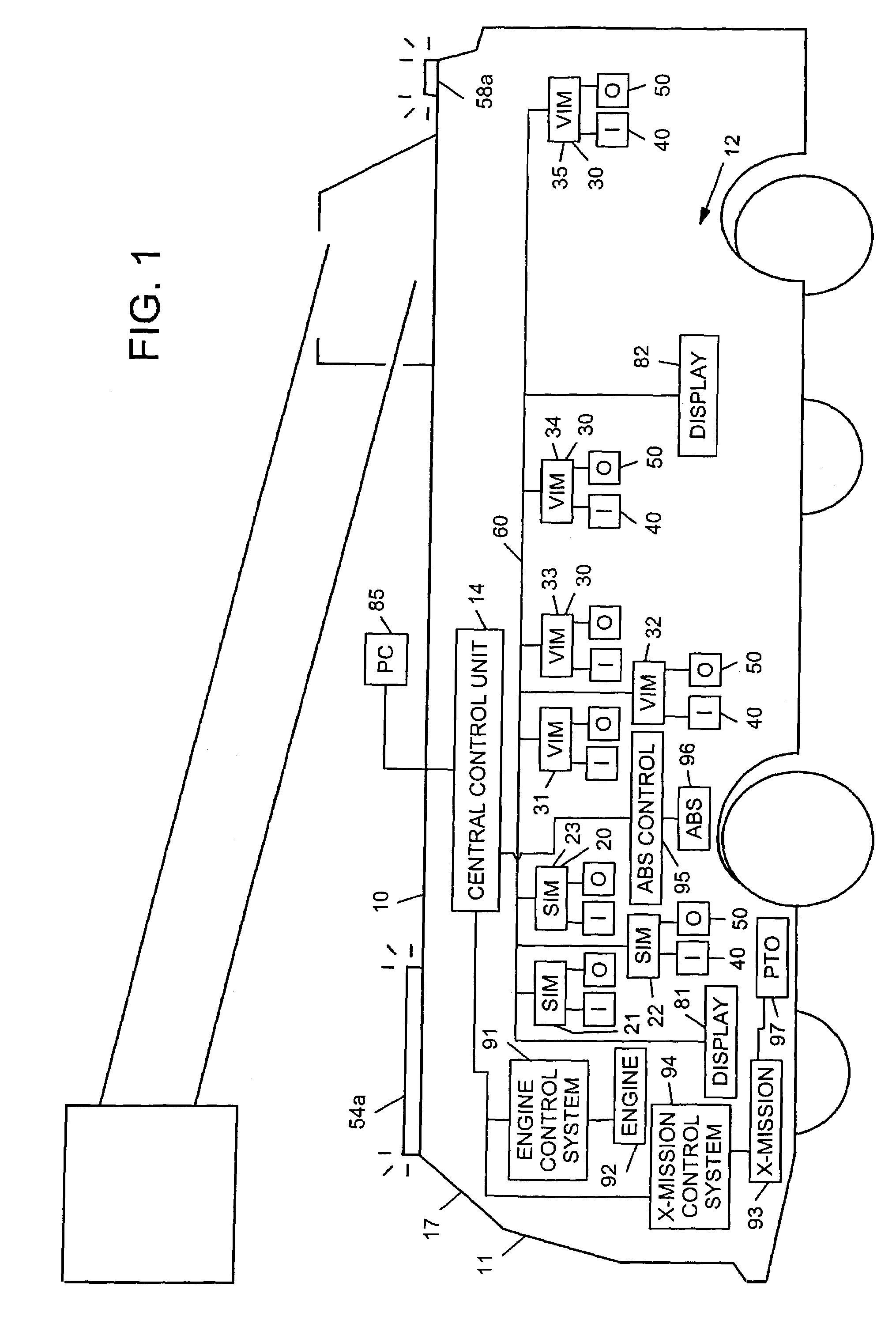
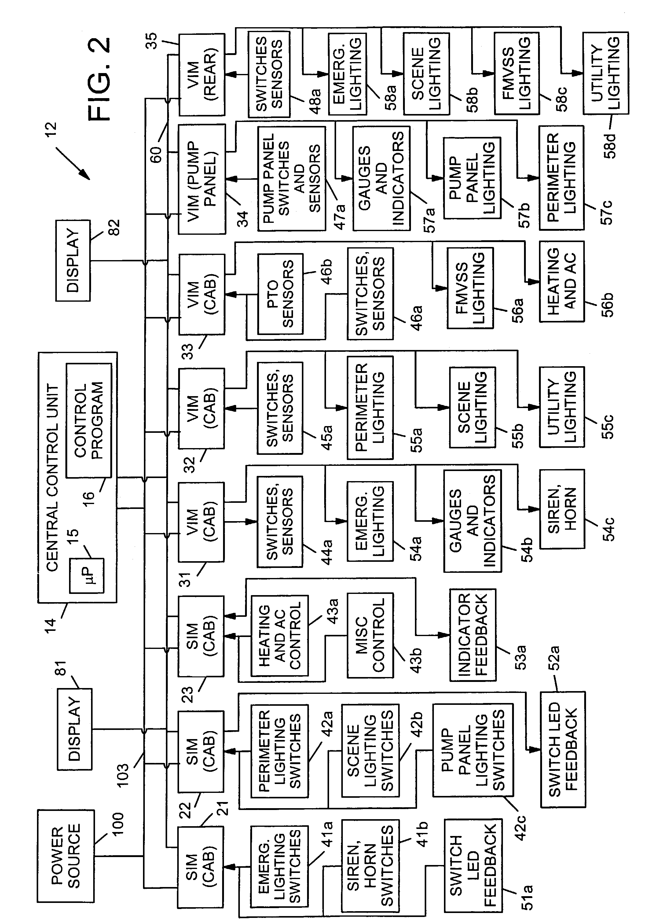
[0069]Patent application Ser. Nos. 09 / 364,690; 09 / 384,393; 09 / 927,946; and 60 / 342,292, upon which priority is claimed, disclose various embodiments of control system architectures in connection with fire trucks, military vehicles, electric vehicles and other types of vehicles and combinations thereof. An advantageous use of a control system of the type disclosed is for service, repair, monitoring, parts ordering, and similar features. For such uses, the control systems described in the above-mentioned applications may be used to control additional output devices associated with the vehicle, and to provide I / O status information which may be transmitted off-board the vehicle, and so on, as described below. For convenience, the contents of the above-mentioned applications is repeated below, followed by a description of service, repair, and monitoring applications which in a preferred embodiment use a control system of a type disclosed in the above-mentioned applications but which coul...


PUM


Abstract

A system comprises an equipment service vehicle and an off-board computer system. The equipment service vehicle further includes a power source, a power transmission link, a plurality of input devices, a plurality of output devices, and an on-board computer system. The on-board computer system further includes a plurality of microprocessor-based interface modules and a communication network. The plurality of interface modules are coupled to the power source by way of the power transmission link and are interconnected to each other by way of the communication network. Each of the plurality of interface modules is coupled to respective ones of the plurality of input devices and the plurality of output devices by way of respective dedicated communication links. The on-board computer system stores I / O status information for the plurality of input devices and the plurality of output devices. The on-board computer system transmits at least some of the I / O status information by way of a wireless radio-frequency communication link to the off-board computer system.

Description

CROSS-REFERENCE TO RELATED APPLICATIONS[0001]This application is a continuation-in-part of U.S. Ser. No. 09 / 927,946, filed Aug. 10, 2001 now U.S. Pat. No. 7,024,296, entitled “Military Vehicle Having Cooperative Control Network With Distributed I / O Interfacing,” pending, which is a continuation-in-part of U.S. Ser. No. 09 / 384,393, filed Aug. 27, 1999, entitled “Military Vehicle Having Cooperative Control Network With Distributed I / O Interfacing,” now U.S. Pat. No. 6,421,593, which is a continuation-in-part of U.S. Ser. No. 09 / 364,690, filed Jul. 30, 1999, entitled “Firefighting Vehicle Having Cooperative Control Network With Distributed I / O Interfacing,” abandoned, each of which is hereby expressly incorporated by reference. This application is also a continuation-in-part of U.S. Ser. No. 09 / 500,506, filed Feb. 9, 2000 now U.S. Pat. No. 6,553,290, entitled “Equipment Service Vehicle Having On-Board Diagnostic System,” allowed, also expressly incorporated by reference. This applicati...

Claims


Application Information

Patent Timeline
IPC IPC(8): G06F7/00G06F19/00A62C27/00B60L3/12B60L50/15B60R16/02B60R16/03B65F3/04G01M17/00G07C5/00G07C5/08G08G1/123
CPCA62C27/00B60L11/12B60R16/0315B65F3/043B65F3/045G01M17/00G07C5/008G07C5/08G07C5/085G08G1/20B60L3/12Y02T90/16B60L2240/70Y02T10/7077Y02T10/7291B60L50/15Y02T10/7072Y02T10/72Y02W30/10
Inventor SQUIRES, BRADLEY C.PILLAR, DUANE R.
Owner OSHKOSH CORPORATION
Learn More