Anchoring member for a support post

a support post and member technology, applied in the direction of rod connection, furniture joining, dwelling equipment, etc., can solve the problem of shoe deformation

Inactive Publication Date: 2007-03-06
KALITEC SIGNALISATION
View PDF18 Cites 23 Cited by
  • Summary
  • Abstract
  • Description
  • Claims
  • Application Information

AI Technical Summary

Benefits of technology

[0008]It is also an aim of the present invention to provide a new post footing having a connecting part which is protected against deformations resulting from the collision of the footing with an obstacle while being driven into a ground surface.

Problems solved by technology

One problem associated with this type of post construction is that when hammered driven into the ground, the shoe can be deformed, for instance, as a result of a collision with an obstacle.
In certain instances, the deformation may be such as to interfere with the subsequent insertion of the connecting member into the shoe, thereby preventing the post section from being mounted onto the shoe.

Method used


Image

  • Anchoring member for a support post
  • Anchoring member for a support post
  • Anchoring member for a support post

Examples


Embodiment Construction

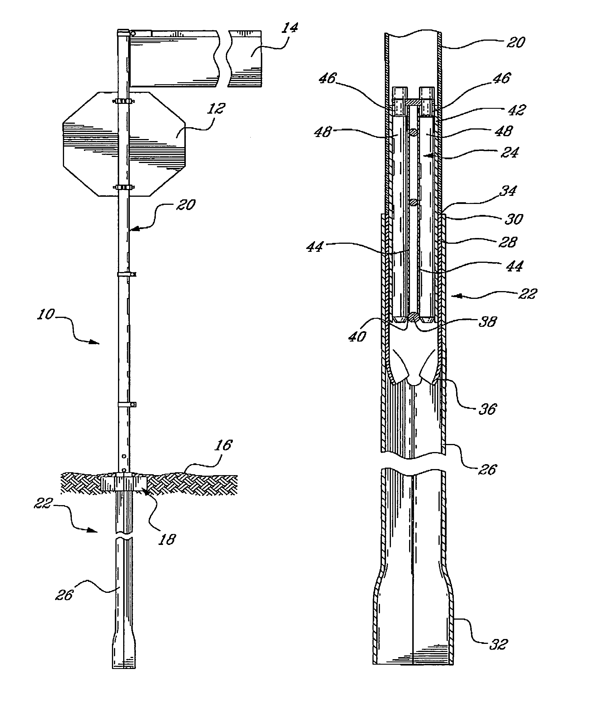
[0016]Now referring to FIG. 1, a post 10 suited for supporting signs 12 and 14 and embodying the elements of the present invention will be described. It is understood that even though the post 10 is herein described as being a signaling post, it could be used without signs 12 and 14 and in any suitable context without departing from the scope of the present invention.

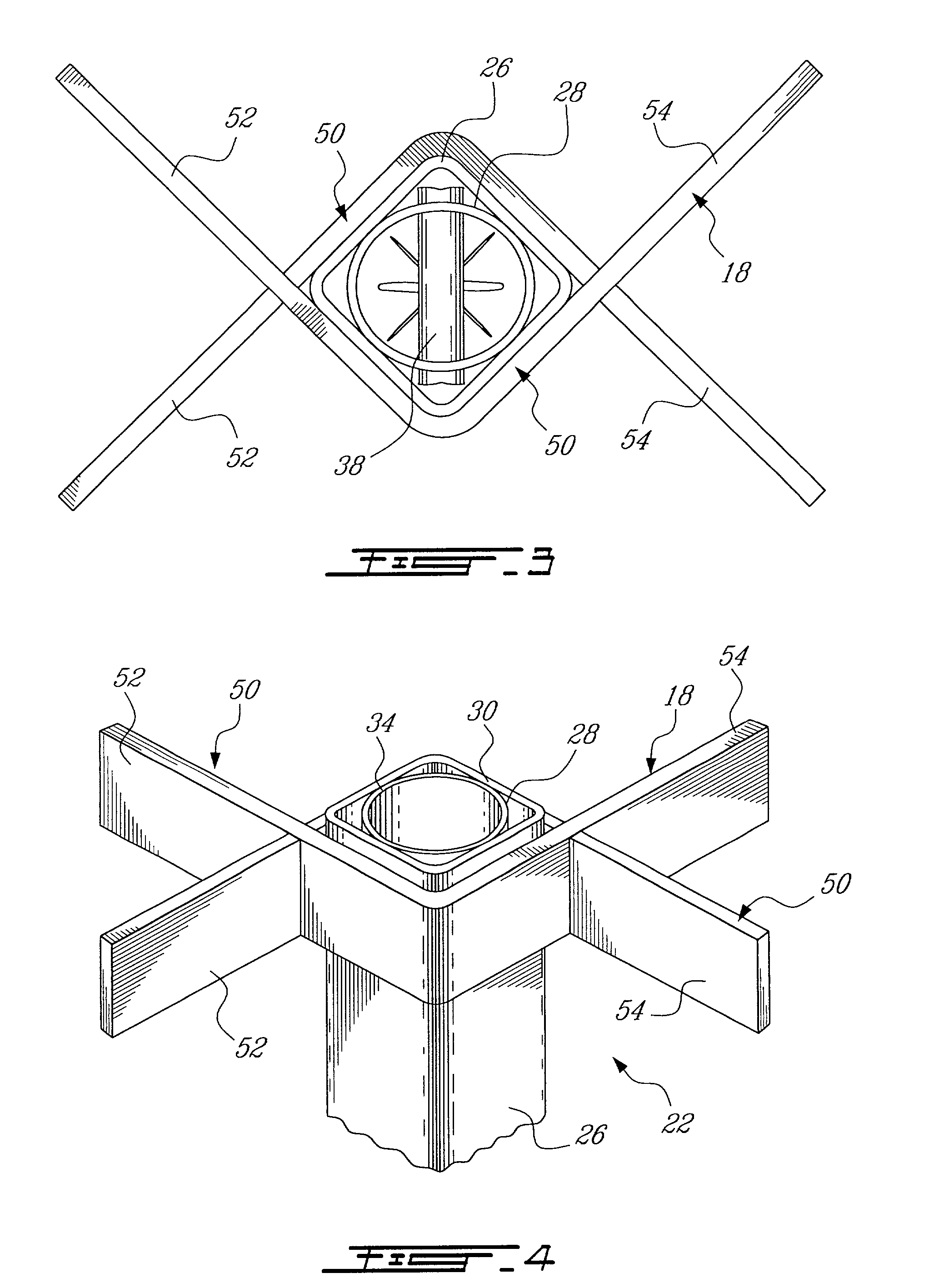
[0017]The post 10 is anchored into a volume of suitable material herein referred to as ground 16. The ground 16 can, for instance, include a layer of asphalt, a layer of compressed crushed rocks or other layers of similar dense material. As will be described hereinbelow, a stabilizer 18 can even be used for allowing the post 10 to be anchored into soft ground surfaces.

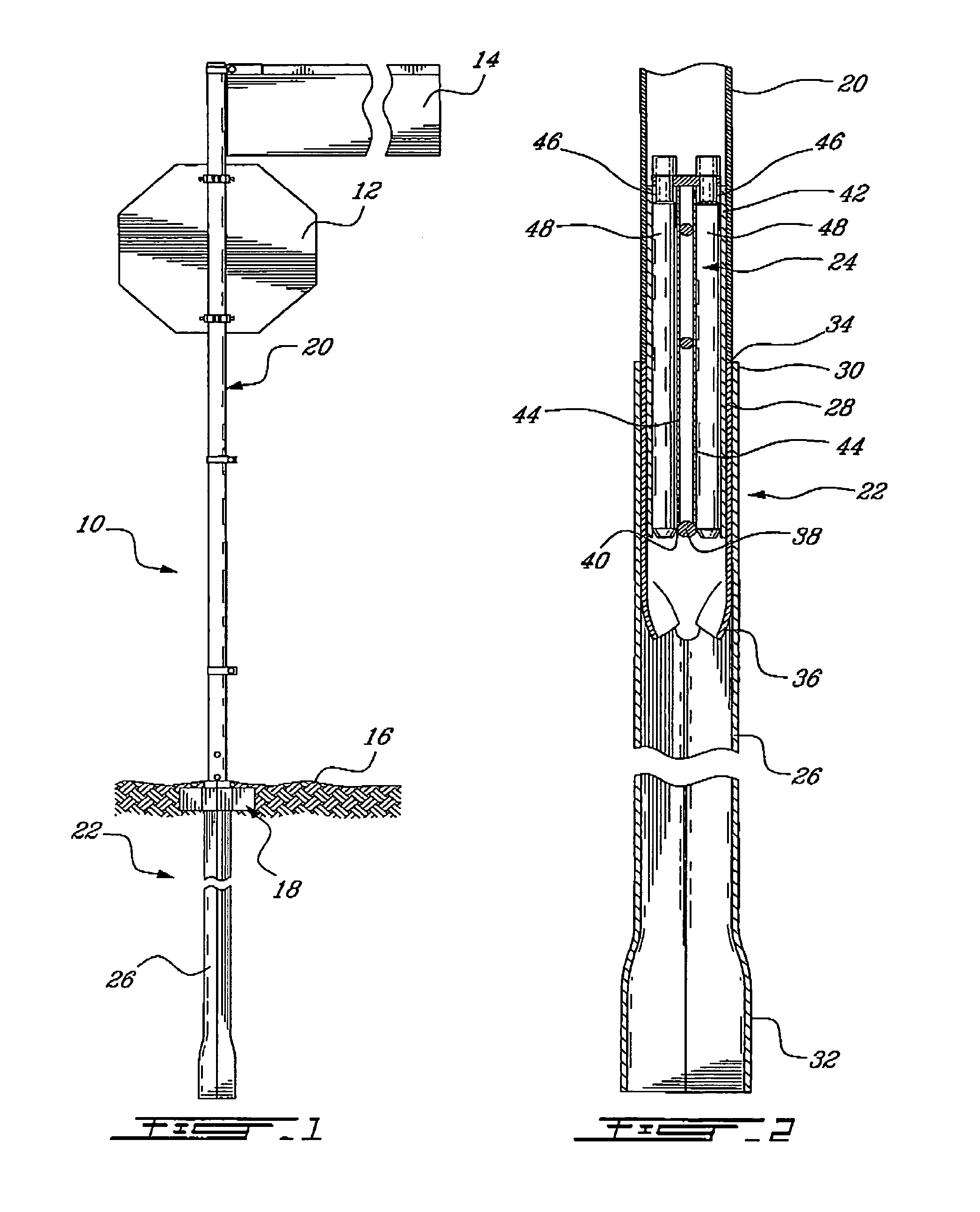
[0018]The post 10 essentially includes an elongated tubular post segment 20 for supporting the signs 12 and 14 at a desired elevation above the ground 16, a footing 22 for anchoring the tubular post segment 20 in the ground 16, and a connector 24 for coupl...


PUM


Abstract

A post footing for holding a post segment above a ground surface comprises an outer sleeve adapted to be forcibly driven into the ground. A socket member is pressure fitted within the outer sleeve with the leading end of the sleeve extending beyond the socket member to prevent the latter from being damaged in the event that an obstacle be encountered while the footing is being driven into the ground. The socket member defines a socket adapted to receive and hold an above-ground post segment once the footing has been installed in the ground.

Description

BACKGROUND OF THE INVENTION[0001]1. Field of the Invention[0002]The present invention relates to post structures and, more particularly, to post footings.[0003]2. Description of the Prior Art[0004]It is known to provide a post with a weakened section that allows the post to bend upon impact according to a predetermined pattern. For instance, U.S. Pat. No. 5,860,253 issued on Jan. 19, 1999 to Lapointe discloses a collapsible post comprising an elongated post section adapted to be connected in an end-to-end relationship with an anchoring member or post shoe driven into the ground. The shoe is provided at an upper end thereof with a socket for receiving and retaining the lower end of a connecting member. Likewise, the upper end of the connecting member is received and held in a socket defined in the lower end of the elongated post section, thereby physically connecting the shoe to the post section.[0005]One problem associated with this type of post construction is that when hammered dr...

Claims


Application Information

Patent Timeline
Patent Type & Authority Patents(United States)
IPC IPC(8): E04H12/22A45F3/44E02D27/42
CPCE02D27/42E04H12/2215Y10T403/557
Inventor LAPOINTE, JEANGRIFFITH, ROBERT
Owner KALITEC SIGNALISATION
Why Eureka
Try Eureka