Screwdriver having a ratchet mechanism

a screwdriver and mechanism technology, applied in screwdrivers, wrenches, manufacturing tools, etc., can solve problems such as inappropriate screwing, and achieve the effect of accurate operation

Inactive Publication Date: 2007-03-06
HU CHENG TSAN
View PDF11 Cites 33 Cited by
  • Summary
  • Abstract
  • Description
  • Claims
  • Application Information

AI Technical Summary

Benefits of technology

[0006]It is the primary objective of the present invention to provide a screwdriver having a ratc

Problems solved by technology

The gear may get damaged easily,

Method used


Image

  • Screwdriver having a ratchet mechanism
  • Screwdriver having a ratchet mechanism
  • Screwdriver having a ratchet mechanism

Examples


Embodiment Construction

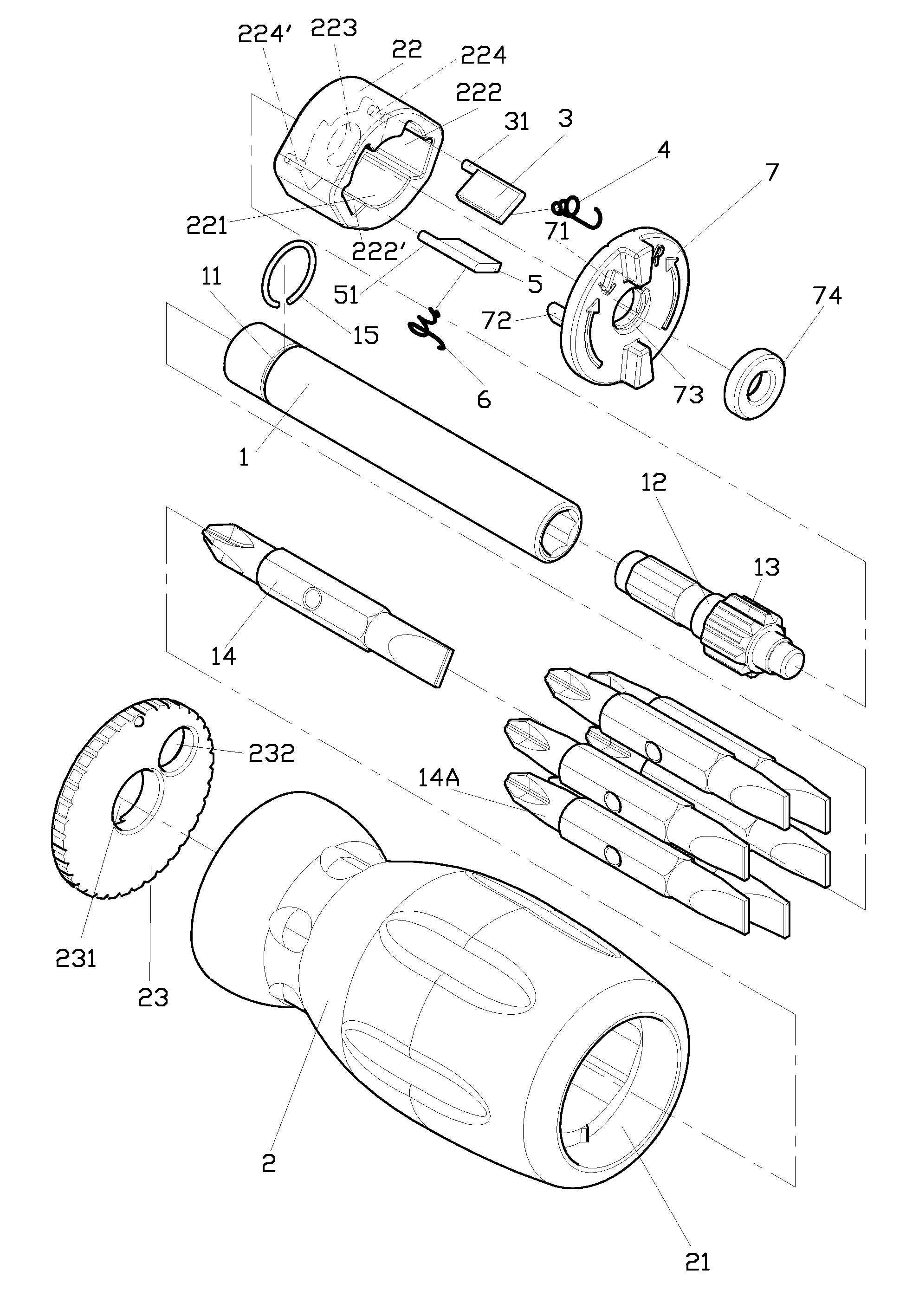
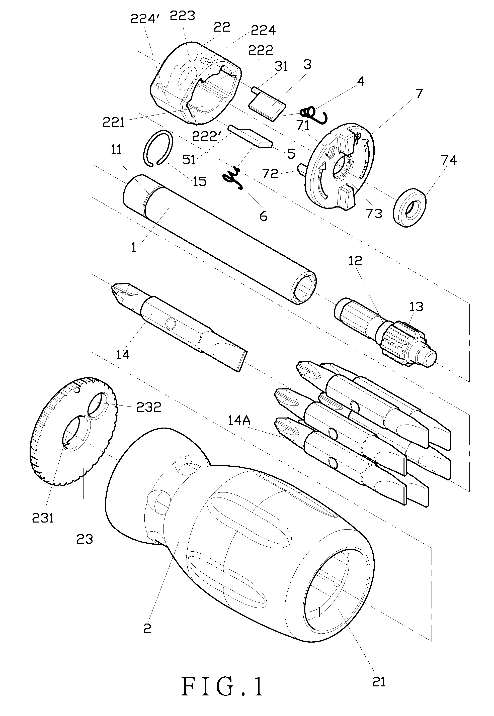
[0015]As shown in FIGS. 1 and 2, a preferred embodiment of the present invention comprises a tool sleeve 1, a handle 2, a first detent 3, a first elastic element 4, a second detent 5, a second elastic element 6, and a switch assembly 7.

[0016]The tool sleeve 1 comprises a groove 11 at a front portion and a ratchet head 12 at a rear end thereof. The tool sleeve 1 has a front end to receive a tool head 14 therein. The ratchet head 12 is formed with ratchet teeth 13 on its outer surface. The tool sleeve 1 may be coupled with other tool heads 14A stored in the handle 2, and a C-shaped fastener 15 is provided on the tool sleeve 1.

[0017]The handle 2 comprises a hollow chamber 21 therein. The tool sleeve 1 is accommodated in a front portion of the chamber 21. A ratchet base 22 is provided in a rear portion of the chamber 21. The ratchet base 22 comprises a compartment 221, a first recess 222, a second recess 222′, an aperture 223, a first hole 224 and a second hole 224′. The compartment 221...


PUM


Abstract

A screwdriver having a ratchet mechanism includes a tool sleeve, a handle, a first detent, a first elastic element, a second detent, a second elastic element, and a switch assembly. The tool sleeve is provided with a ratchet head formed with ratchet teeth. The handle has a hollow chamber to accommodate the tool sleeve and a ratchet base therein. The ratchet base is to accommodate the ratchet head with the ratchet teeth, the detents and the elastic elements. Each of the detents engages with the ratchet teeth of the ratchet head. The switch assembly is pivotally connected to the handle and comprises a first stud and a second stud to engage with the first detent and the second detent, respectively.

Description

BACKGROUND OF THE INVENTION[0001]1. Field of the Invention[0002]The present invention relates to a screwdriver having a ratchet mechanism, in particular to a ratchet mechanism provided in a rear portion of a handle to prevent it from touching accidentally by means of a switch assembly having studs to link a detent at one side to disengage from ratchet teeth of a ratchet head so as to change the turning direction of a tool sleeve.[0003]2. Description of the Prior Art[0004]There are various ratchet hand tools on the market. Each has its special function, such as U.S. Pat. No. 5,875,693 (incorporated herein by reference) which uses a gear to secure and to change the turning direction. The gear may get damaged easily, causing meshing inappropriately.[0005]A ratchet mechanism for a screwdriver, such as U.S. Pat. Nos. 6,070,503, 6,253,654 and 6,854,363, (all of which are incorporated herein by reference) is provided at a front portion or at a front end of a handle, which may accidentally ...

Claims


Application Information

Patent Timeline
IPC IPC(8): B25B13/46B25B15/04B25B15/00
CPCB25B13/463B25G1/085B25B15/04
Inventor HU, CHENG-TSAN
Owner HU CHENG TSAN
Why Eureka
Try Eureka