Apparatus and method for mechanically reinforcing the welds between riser pipes and riser braces in boiling water reactors

a technology of riser braces and riser pipes, which is applied in the direction of auxillary welding devices, nuclear elements, greenhouse gas reduction, etc., can solve the problems of riser braces going into resonance, affecting the mechanical fatigue potentially becoming unstable to the detriment of the jet pump assembly,

Active Publication Date: 2007-03-06
MPR ASSOC
View PDF16 Cites 28 Cited by
  • Summary
  • Abstract
  • Description
  • Claims
  • Application Information

AI Technical Summary

Benefits of technology

[0020]The present invention overcomes the problems associated with cracked welds between riser pipes and riser braces in jet pump assemblies of boiling water reactors. The present invention provides a repair for a cracked weld between a riser brace and riser pipe of a jet pump assembly in a boiling water reactor involving mechanically clamping the riser pipe to the riser brace. The present invention provides redundant structural support to the weld between a riser pipe and riser brace of a jet pump assembly in a boiling water reactor. The clamp assembly of the present invention applies a compressive load between a riser pipe and the yoke of a riser brace of a jet pump assembly in a boiling water reactor while staying close to the footprint of the riser brace. The present invention provides an alternate load path for loads from a riser pipe to a riser brace and ultimately to the attachment wall to which the riser brace is attached in a boiling water reactor. The present invention ensures that a riser pipe and a riser brace of a jet pump assembly in a boiling water reactor are held together in the event that the weld between the riser pipe and riser brace fails.
[0021]Some of the advantages of the present invention are that the clamp assembly can be installed remotely from a refueling bridge using long-handled tooling; the clamp assembly utilizes corrosion resistant materials; the clamp assembly is installed on the riser pipe and riser brace without requiring welding or electric discharge machining; installation of the clamp assembly is simplified through the use of a main bolt or connecting member and a draw bolt or operating member; the connecting member carries compressive loads applied to opposed attachment members of the clamp assembly which attach to the riser brace; a pivotal clamp body is associated with each attachment member to apply radial forces to the riser pipe; the radial load applied by the clamp bodies is adjustable via the operating member which connects the clamp bodies; the attachment members are adjustable via the connecting member which connects the attachment members; the attachment members include respective retaining members for respectively engaging the side members of the riser brace to constrain the riser brace against movement; the attachment members include engagement elements or shear tabs along the yoke of the riser brace to react the radial forces applied by the clamp bodies; the clamp assembly avoids interfering with the jet pump mixers and / or other internals or equipment installed in the reactor vessel for future repairs or inspections; and the clamp assembly and method of the present invention allow cracked welds between the riser pipes and riser braces of jet pump assemblies to be repaired rather than replaced, thereby avoiding the disadvantages of replacement including greater cost, longer down times and the potential for radiation exposure.

Problems solved by technology

If the vane passing frequency of the recirculation pumps equals or exceeds the natural frequency of the riser brace, the riser brace will go into resonance and potentially become unstable to the detriment of the jet pump assembly.
Cracks initiated by IGSCC or other causes in the welds between the riser braces and the riser pipes may grow in size and reach critical sizes for mechanical fatigue resulting from the vane passing frequencies of the recirculation pumps exceeding the excitation frequency of the riser braces.

Method used


Image

  • Apparatus and method for mechanically reinforcing the welds between riser pipes and riser braces in boiling water reactors
  • Apparatus and method for mechanically reinforcing the welds between riser pipes and riser braces in boiling water reactors
  • Apparatus and method for mechanically reinforcing the welds between riser pipes and riser braces in boiling water reactors

Examples


Embodiment Construction

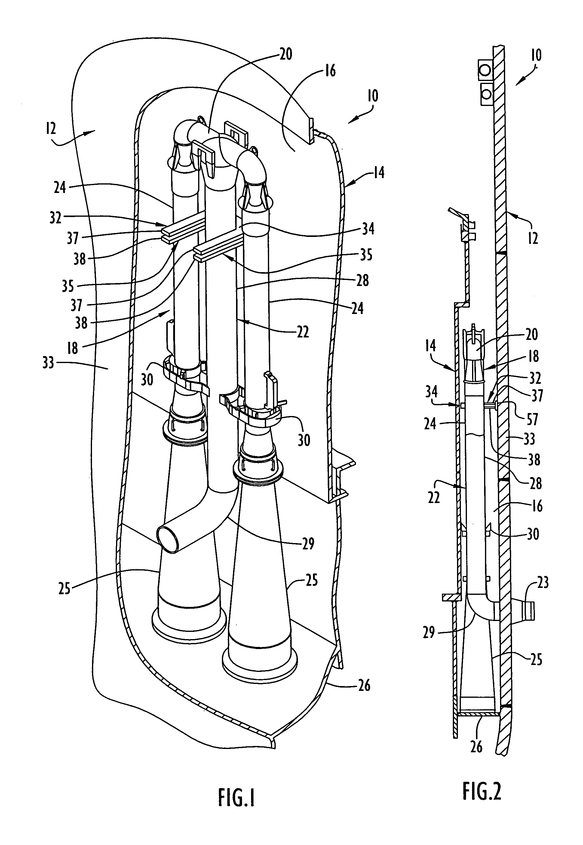
[0033]A boiling water reactor 10 is illustrated in FIGS. 1 and 2 and comprises a reactor pressure vessel 12 and a core shroud 14 disposed within the reactor pressure vessel 12 with there being an annular region or space 16 known as the downcomer annulus between the core shroud and the reactor pressure vessel. A jet pump assembly 18 of the boiling water reactor 10 is disposed in the annular region 16 between the reactor pressure vessel 12 and the core shroud 14. A more detailed explanation of the structure and operation of boiling water reactor 10 is found in U.S. Pat. No. 6,264,203 B1 to Weems et al, the entire disclosure of which is incorporated herein by reference.

[0034]The jet pump assembly 18 comprises a transition piece 20, a riser 22 extending downwardly from the transition piece to a recirculation inlet nozzle 23 along the exterior of the reactor pressure vessel wall, and a pair of inlet mixers 24 extending downwardly from the transition piece to a pair of diffusers 25 mounte...


PUM


Abstract

An apparatus and method for mechanically reinforcing the weld between a riser pipe and riser brace of a jet pump assembly are characterized by first and second attachment members for attachment on a riser brace of the jet pump assembly, and first and second clamp bodies respectively pivotally mounted on the attachment members for movement to a clamping position. In the clamping position, respective abutment surfaces of the clamp bodies are forced against a riser pipe that is attached to a yoke of the riser brace. The abutment surfaces apply radial forces to the riser pipe, and the radial forces are reacted by forces applied against the yoke by respective engagement elements of the attachment members whereby the riser pipe and riser brace are clamped together between the abutment surfaces and the engagement elements.

Description

BACKGROUND OF THE INVENTION[0001]1. Field of the Invention[0002]The present invention relates generally to reinforcing the welds between riser pipes and riser braces in jet pump assemblies of boiling water reactors. In particular, the present invention relates to apparatus and methods for mechanically reinforcing the welds between riser pipes and riser braces by clamping the riser pipes to the riser braces.[0003]2. Discussion of the Related Art[0004]A typical boiling water reactor includes a reactor vessel, a core shroud disposed within the reactor vessel, and a core comprising a plurality of fuel assemblies disposed within the core shroud. An annular region or space between the core shroud and the reactor vessel is known as the downcomer annulus. Feedwater enters the reactor vessel via a feedwater inlet and is distributed circumferentially within the reactor vessel by a feedwater sparger. The feedwater mixes with other water coming from steam separators of the reactor and flows dow...

Claims


Application Information

Patent Timeline
Patent Type & Authority Patents(United States)
IPC IPC(8): B23K37/00B23K37/053
CPCB23K37/0533G21C15/25Y02E30/31B23K2201/06B23K2101/06Y02E30/30
Inventor BUTLER, PATRICK J.
Owner MPR ASSOC
Why Eureka
Try Eureka