Hermetic lid seal by metal pressing for fiber optic module
a fiber optic module and lid sealing technology, applied in the field of optics, can solve problems such as complex manufacturing equipment or processes, and achieve the effect of reducing or eliminating moisture penetration
- Summary
- Abstract
- Description
- Claims
- Application Information
AI Technical Summary
Benefits of technology
Problems solved by technology
Method used
Image

Examples
first embodiment
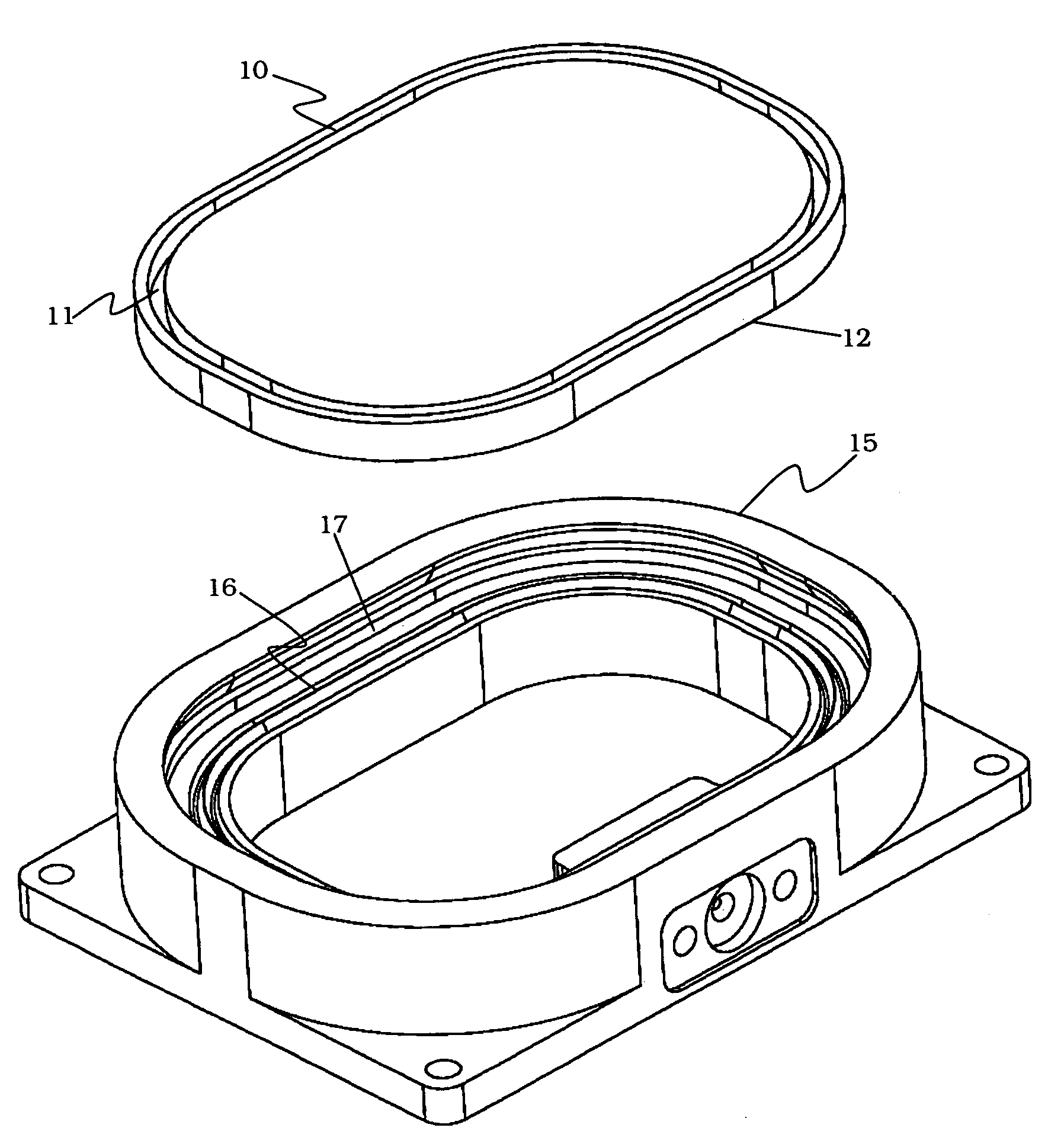
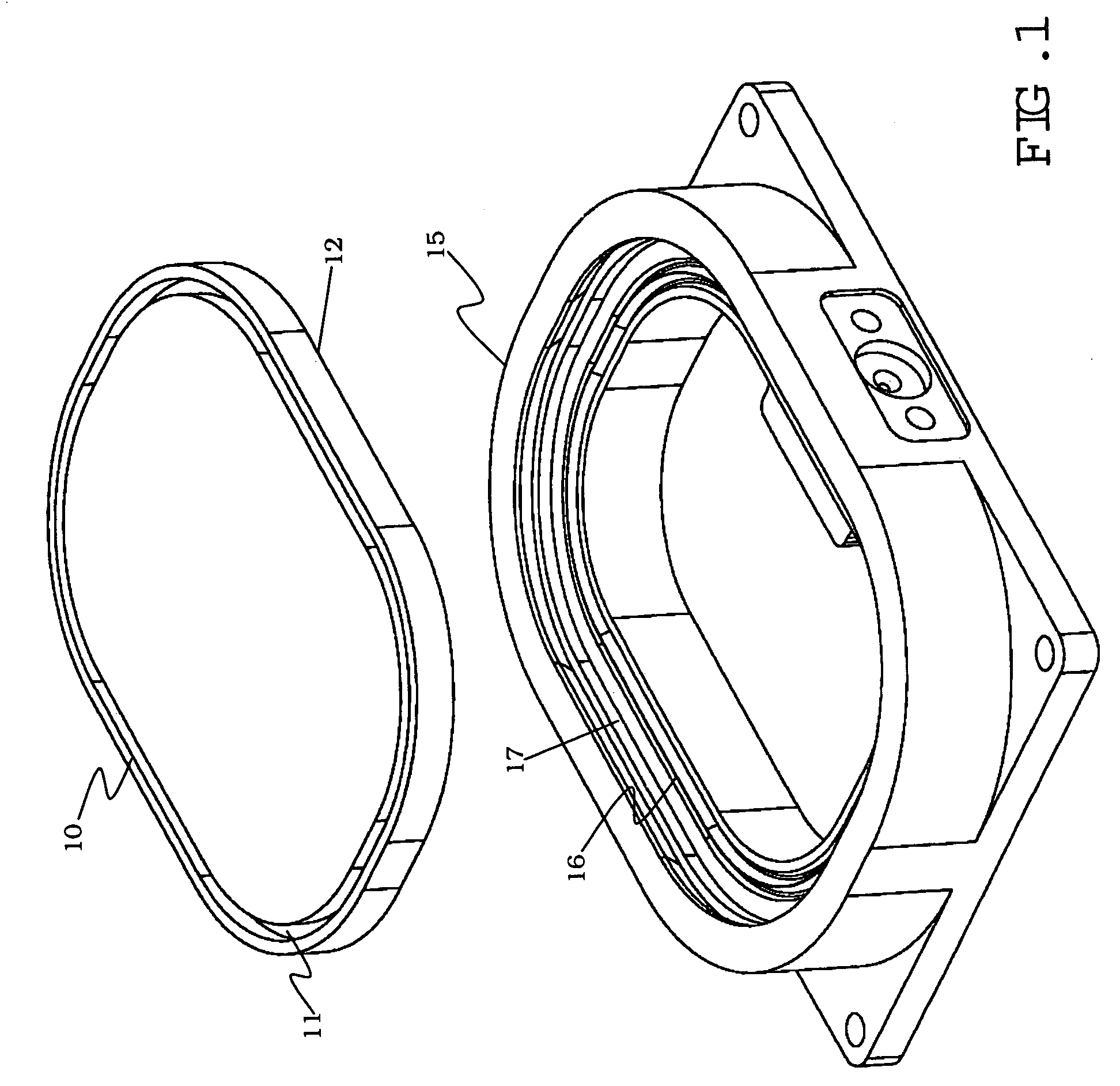
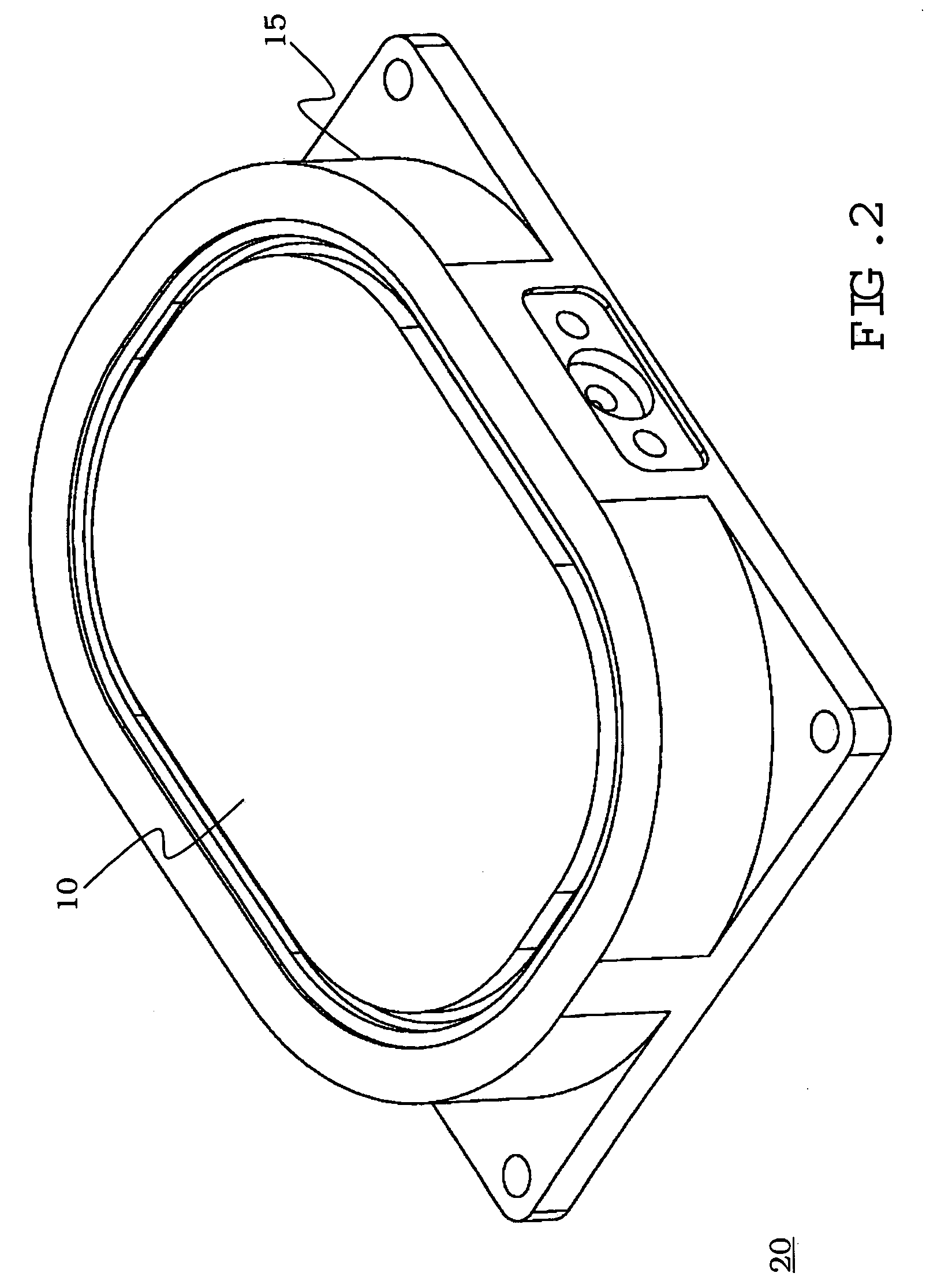
[0026]Referring now to FIG. 1, there is shown a structural diagram illustrating a first embodiment in an exploded ISO view of a lid 10 and a module housing 15 before sealing in accordance with the present invention. The dimension of the lid 10 is suitable for placement into the module housing 15. The lid 10 has a cylindrical-shaped slot 11 that is cut near the edge of the lid 10 for serving as a holding mechanism between the lid 10 and the module housing 15 after compression. The cylindrical-shaped slot 11 resembles a running track that extends all the way around the lid 10.
[0027]The module housing 15 has a knife-shaped edge 16 surrounding the interior of the module housing 15 for biting into the lid 10 to form a sealing mechanism. In this embodiment, the knife-shaped edge 16 protrudes upward for making contact with a bottom surface 12 of the lid 10 when the lid 10 is placed over the module housing 15. The knife-shaped edge 16 resembles a sharp edge that has a knife-edge quality whi...
second embodiment
[0034]Referring now to FIG. 7, there is shown a structural diagram illustrating a second embodiment in an exploded ISO view of a lid 70 and a module housing 75 before sealing in accordance with the present invention. The dimension of the lid 70 is suitable for placement into the module housing 75. The lid 70 has a curved surface 71 around the outer edge of the lid 70 for serving as a holding mechanism between the lid 70 and the module housing 75 after compression.
[0035]The module housing 75 also has a knife-shaped edge 76 surrounding the interior of the module housing 75 for biting into the lid 70 to form a sealing mechanism, similar to the knife-shaped edge 16 in the module housing 15 as described with respect to FIG. 1. The knife-shaped edge 76 protrudes upward for making contact with a bottom surface 72 of the lid 70 when the lid 70 is placed over the module housing 75. The knife-shaped edge 76 resembles a sharp edge that has a knife-edge quality which is able to bite into the bo...
third embodiment
[0043]Turning now to FIG. 14, there is shown a structural diagram illustrating the third embodiment in an exploded cross-sectional view of the lid 120 and the module housing 125 before sealing in accordance with the present invention. In this embodiment, the module housing 125 has a knife-shaped edge 140 where the tip of the knife-edge is at the same height as the top surface of the module housing 125. The lid 120 has a slot 145 for placement over the knife-edge 140. The sealing mechanism between the lid 120 and the module housing 145 is formed when pressure is exerted on the lid so that the knife-edge 140 bites into the lid 120. The plurality of screws 122 serve as a holding mechanism between the lid 120 and the module housing 125 when the plurality of screws 122 are pressed through the holes 121 of the lid and into the module housing 125.
[0044]FIG. 15 is a structural diagram illustrating the third embodiment in an exploded cross-sectional view of the lid 120 and the module housing...
PUM
 Abstract
Description
Claims
Application Information
 - R&D
- Intellectual Property
- Life Sciences
- Materials
- Tech Scout
- Unparalleled Data Quality
- Higher Quality Content
- 60% Fewer Hallucinations
Browse by: Latest US Patents, China's latest patents, Technical Efficacy Thesaurus, Application Domain, Technology Topic, Popular Technical Reports.
© 2025 PatSnap. All rights reserved.Legal|Privacy policy|Modern Slavery Act Transparency Statement|Sitemap|About US| Contact US: help@patsnap.com