Handle attachment, assist mechanism therefor, and electrical switching apparatus employing the same

a technology of electrical switching apparatus and handle attachment, which is applied in the direction of manual control with single controlling member, mechanical control device, instruments, etc., can solve the problems of not all handle attachments are closely coupled, the operating member b>16/b> is excessively biased, and the known handle attachments suffer from a number of disadvantages, etc., to achieve the effect of adequate energy and facilitate the movement of the operating member

Active Publication Date: 2007-03-06
EATON INTELLIGENT POWER LTD
View PDF11 Cites 56 Cited by
  • Summary
  • Abstract
  • Description
  • Claims
  • Application Information

AI Technical Summary

Benefits of technology

[0013]These needs and others are met by the present invention, which is directed to an assist mechanism for handle attachments coupled to electrical switching apparatus. The assist mechanism combines a unique shape and resilient properties to facilitate movement of the operating member of electrical switching apparatus, such as circuit breakers, and to assure that adequate energy is generated in order to move the handle of the handle attachment to a corresponding position.

Problems solved by technology

When the handle attachment is attached directly to the face of the molded case circuit breaker, such a configuration is commonly referred to as “closely-coupled.” However, not all handle attachments are closely-coupled.
However, known handle attachments, including those previously described, suffer from a number of disadvantages.
Therefore, use of such a spring as a handle assist mechanism could result in the operating member 16 being excessively biased, for example, from the ON position or the tripped position toward the OFF position.
In other words, a slight bump or other disruption of the circuit breaker 4 or handle attachment 2 could, for example, result in the circuit breaker 4 being undesirably, unintentionally turned OFF.
This problem could also occur with relatively small circuit breakers having other operating member configurations (e.g., two-position operating members).

Method used


Image

  • Handle attachment, assist mechanism therefor, and electrical switching apparatus employing the same
  • Handle attachment, assist mechanism therefor, and electrical switching apparatus employing the same
  • Handle attachment, assist mechanism therefor, and electrical switching apparatus employing the same

Examples


Embodiment Construction

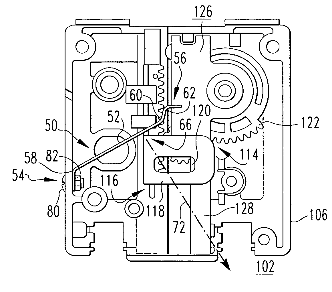
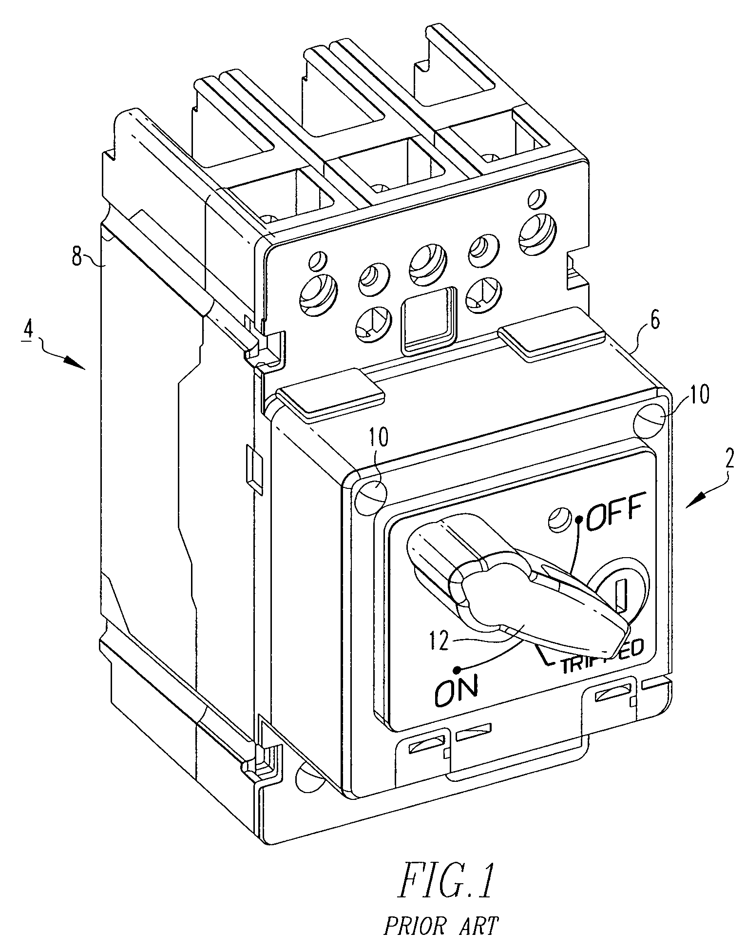
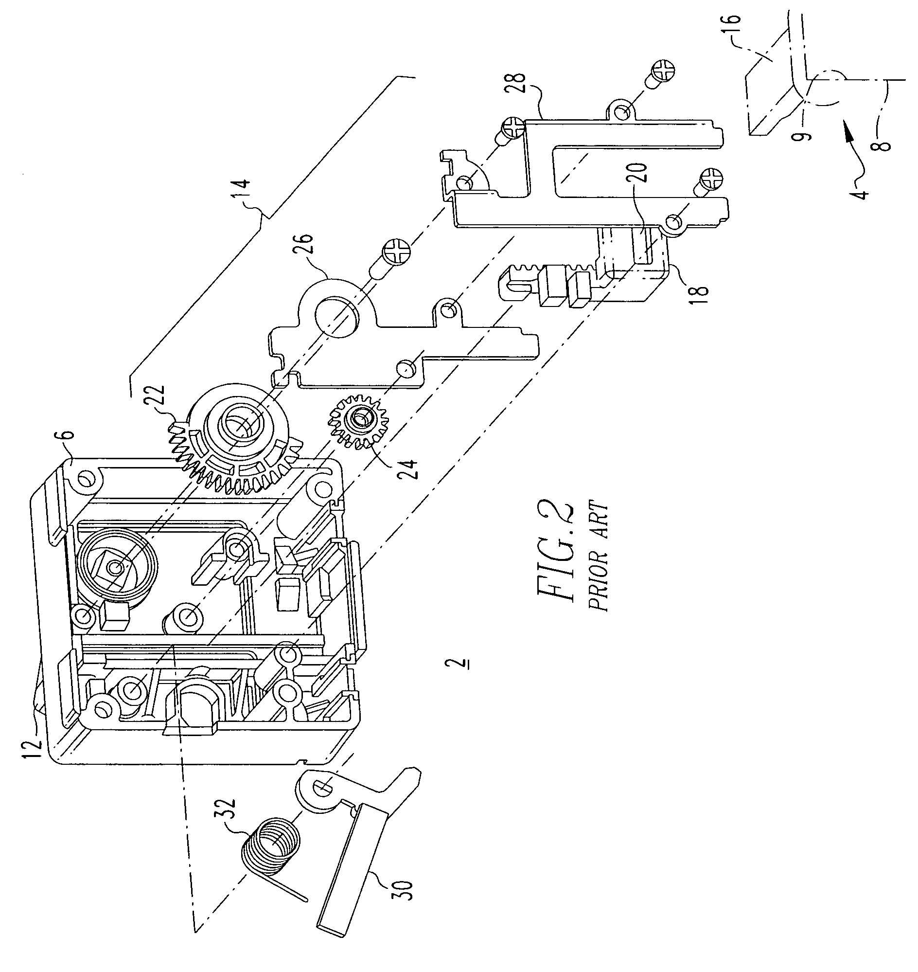
[0031]For purposes of illustration, the invention will be described as applied to a closely-coupled trip indicator for a molded case circuit breaker, although it will become apparent that it could also be applied to other types of electrical switching apparatus (e.g., without limitation, circuit switching devices and other circuit interrupters such as contactors, motor starters, motor controllers and other load controllers) having an operating mechanism, and to other types of handle attachments (e.g., non-closely coupled actuating levers and indicators) coupled thereto.

[0032]Directional phrases used herein, such as, for example, left, right, clockwise, counterclockwise and derivatives thereof, relate to the orientation of the elements shown in the drawings and are not limiting upon the claims unless expressly recited therein.

[0033]As employed herein, the term “fastener” refers to any suitable connecting or tightening mechanism expressly including, but not limited to, screws, bolts a...


PUM


Abstract

An assist mechanism is for a handle attachment of a circuit breaker having a housing with an operating member operable among a plurality of positions. The handle attachment includes a casing coupled to the circuit breaker housing and enclosing an actuating assembly which interconnects the circuit breaker operating member with a handle that is operable from the exterior of the casing. The assist mechanism is a wave spring having a first end coupled to the casing, and a second end having a wave bend that divides the second end into three sections having three corresponding tangential vector forces. The tangential vector forces provide a bias to the actuating assembly of the handle attachment that differs depending on the position of the circuit breaker operating member. In this manner, the assist mechanism augments energy generated by movement of the operating member and translates it into a corresponding handle attachment movement.

Description

BACKGROUND OF THE INVENTION[0001]1. Field of the Invention[0002]The present invention relates generally to electrical switching apparatus and, more particularly to a handle attachment for an electrical switching apparatus, such as a circuit breaker. The invention also relates to an assist mechanism for handle attachments and to electrical switching apparatus having handle attachments with assist mechanisms.[0003]2. Background Information[0004]Circuit breakers are generally old and well known in the art. Examples of circuit breakers are disclosed in U.S. Pat. Nos. 5,341,191 and 5,471,184. Circuit breakers are used to protect electrical circuitry from damage due to a trip condition, such as, for example, an overcurrent condition, an overload condition, an undervoltage condition, or a relatively high level short circuit or fault condition. Molded case circuit breakers, for example, include at least one pair of separable contacts which are operated either manually by way of a handle dis...

Claims


Application Information

Patent Timeline
Patent Type & Authority Patents(United States)
IPC IPC(8): H01H9/06
CPCG05G1/04G05G5/06H01H71/56G05G7/02H01H2071/565H01H9/281
Inventor TURNER, DAVID C.
Owner EATON INTELLIGENT POWER LTD
Why Eureka
Try Eureka