Physical condition monitoring system

a monitoring system and physical condition technology, applied in the field of physical condition monitoring systems, can solve problems such as indirect detection

Inactive Publication Date: 2007-03-06
KK TOKAI RIKA DENKI SEISAKUSHO
View PDF14 Cites 24 Cited by
  • Summary
  • Abstract
  • Description
  • Claims
  • Application Information

AI Technical Summary

Problems solved by technology

However, the above apparatus and system only indirectly detects a driver dozing off using an imaging means, such as the CCD camera.

Method used


Image

  • Physical condition monitoring system
  • Physical condition monitoring system
  • Physical condition monitoring system

Examples


Embodiment Construction

[0016]A physical condition monitoring system 1 according to a preferred embodiment of the present invention will now be described.

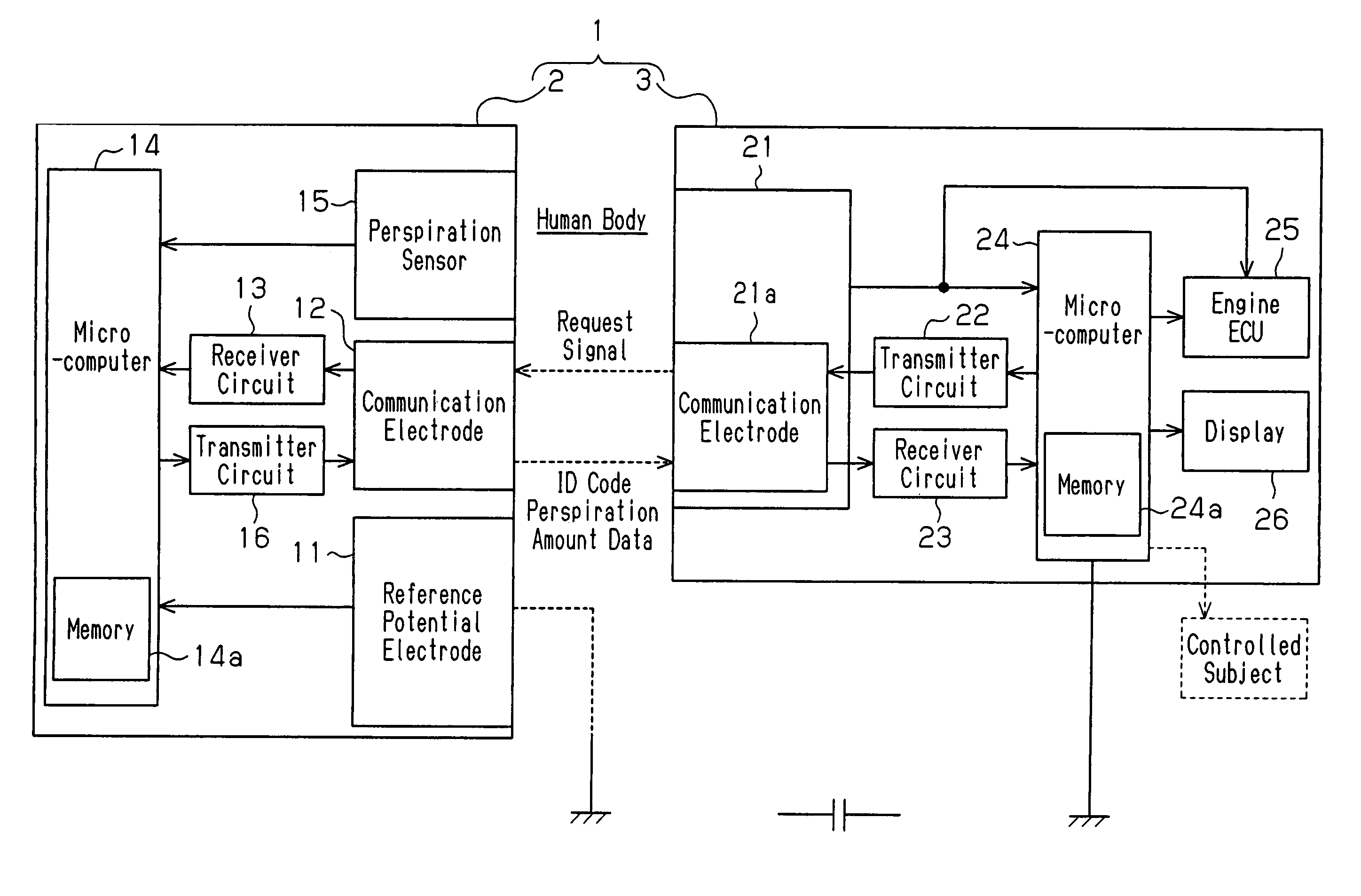
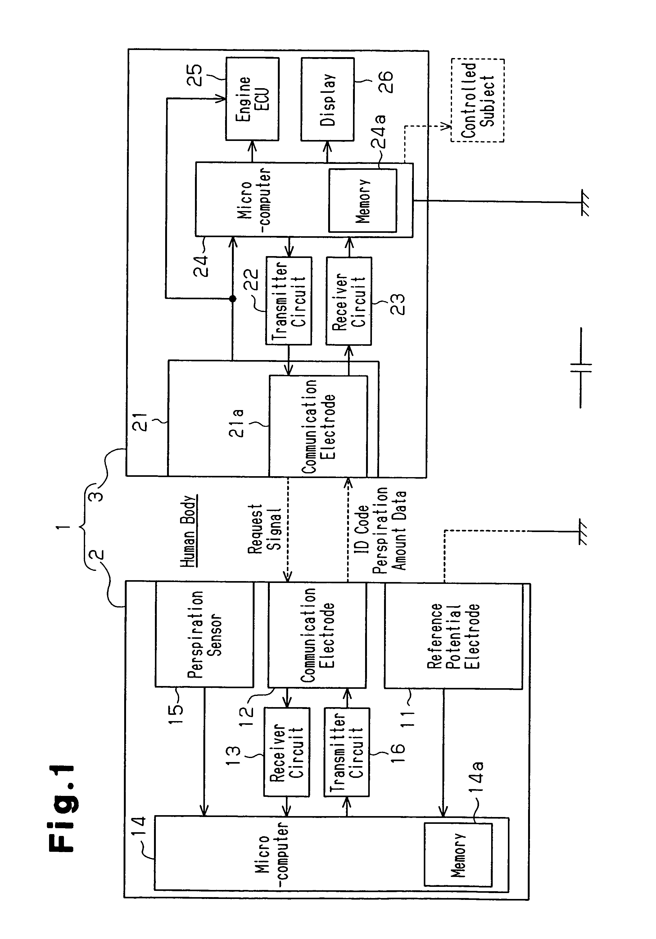
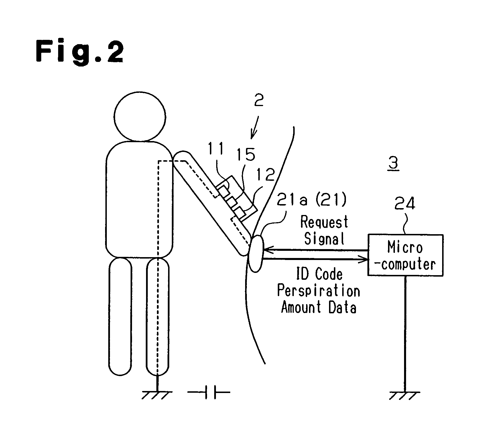
[0017]As shown in FIG. 1, the physical condition monitoring system 1 includes a portable device 2 and a vehicle monitoring device 3. The portable device 2 is carried by the driver. The portable device 2 of the preferred embodiment is configured in the form of a wrist watch. The driver wears the portable device 2 by wrapping it around his or her arm. When the driver wears the portable device 2 in this manner, the rear surface of the portable device 2 comes into close contact with the driver's arm. The vehicle monitoring device 3 is installed in an automobile and includes an engine start switch 21. The physical condition monitoring system 1 is configured to enable two-way communication between the portable device 2 and the vehicle monitoring device 3. In the physical condition monitoring system 1 of the preferred embodiment, when the driver wearing the port...


PUM


Abstract

A system that directly monitors a physical condition of a driver. The system includes a portable device carried by the driver. The portable device includes a perspiration sensor, for detecting biological information serving as an index representing the physical condition of the driver, and a transmitter circuit, for generating a transmission signal including the biological information detected by the perspiration sensor. The monitoring device, which is installed in the vehicle, includes a receiver circuit for receiving the transmission signal from the portable device. A microcomputer and a display inform the driver of his or her physical condition based on the transmission signal received by the receiver circuit.

Description

BACKGROUND OF THE INVENTION[0001]The present invention relates to a system for monitoring a physical condition, and more specifically, to a system for monitoring the physical condition of a driver of a vehicle.[0002]Recently, a vehicle provided with an on-vehicle camera for detecting a driver dozing off has been proposed.[0003]Japanese Laid-Open Patent Publication No. 2003-104126 describes a vehicle passenger compartment monitoring apparatus, which includes a camera attached to a rearview mirror (vehicle interior). The camera generates an image of the passenger compartment, and a computer analyzes the generated image. The vehicle passenger compartment monitoring apparatus detects the driver dozing off based on the analyzed result.[0004]Japanese Laid-Open Patent Publication No. 2000-016181 describes a vehicle periphery recognition system, which includes a CCD camera arranged on a rearview mirror attached to a door (vehicle exterior). The CCD camera generates an image of a traffic lan...

Claims


Application Information

Patent Timeline
Patent Type & Authority Patents(United States)
IPC IPC(8): G08B23/00A61B5/00A61B5/022A61B5/0245A61B5/16A61B5/18G08B21/06
CPCG08B21/06
Inventor HAYASHI, MASAKIIWASAKI, YUKIO
Owner KK TOKAI RIKA DENKI SEISAKUSHO
Why Eureka
Try Eureka