Cardiac catheter imaging system

a catheter imaging and catheter technology, applied in the field of catheters, can solve the problems of ineffective current pharmacological treatment for managing cardiac arrhythmias, intractable heartbeat, and significant morbidity and mortality, and achieve the effect of improving pharmacological or non-pharmacological treatment and improving the understanding of the mechanism

Inactive Publication Date: 2007-03-06
KHOURY DIRAR S
View PDF12 Cites 156 Cited by
  • Summary
  • Abstract
  • Description
  • Claims
  • Application Information

AI Technical Summary

Benefits of technology

The present invention is a method for improving the understanding of abnormal heartbeats and developing better therapies for them. The method uses little fluoroscopy and allows for the study of rare or chaotic rhythm disorders. It also allows for accurate guidance of diagnostic and therapeutic catheters within a realistic model of the heart derived from ultrasound, infrared, or magnetic resonance. The invention has significant advantages in guiding clinical procedures and providing hemodynamic assessment.

Problems solved by technology

The patent text discusses the challenges in managing cardiac arrhythmias and the limitations of current mapping techniques in identifying the causes of abnormal heart rhythms. The technical problem addressed in the text is the need for improved mapping techniques that can accurately identify the anatomical sources of abnormal heart rhythms and deliver appropriate therapy. The text describes the endocardial electrocardiographic approach, which can provide true images of endocardial anatomy and the geometrical relationship between the probe and the heart. The invention aims to solve the problem by developing a noncontact electrode mapping system that can accurately locate the source of abnormal heart rhythms and deliver appropriate therapy.

Method used


Image

  • Cardiac catheter imaging system
  • Cardiac catheter imaging system
  • Cardiac catheter imaging system

Examples


Embodiment Construction

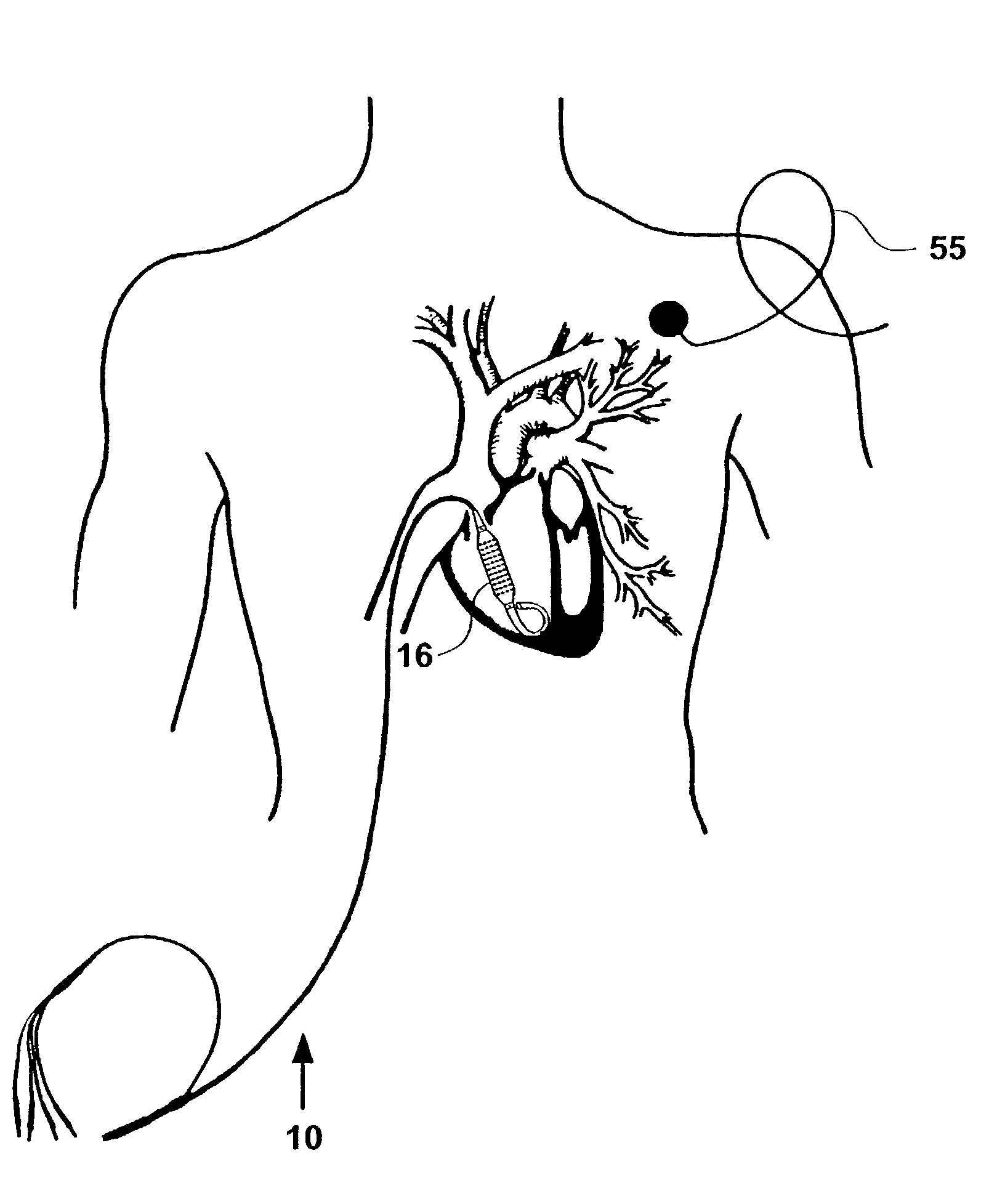
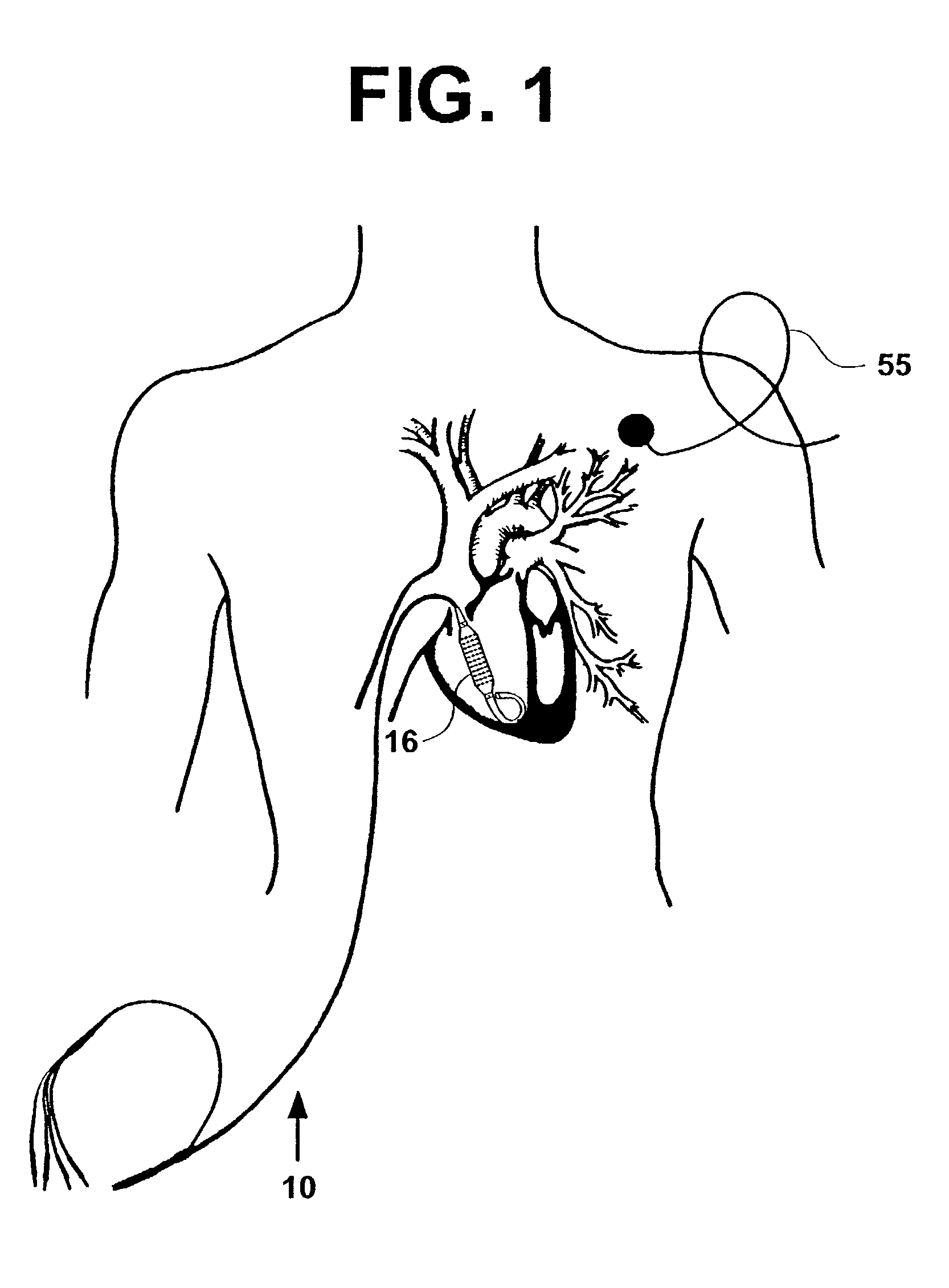
[0079]FIG. 1 illustrates an electrical-anatomical imaging catheter-system 10 in use in a human patient. The catheter is percutaneously inserted through a blood vessel (vein or artery) and advanced into the heart cavity. The catheter detects both electrical and anatomical properties of interior heart tissue (endocardium).

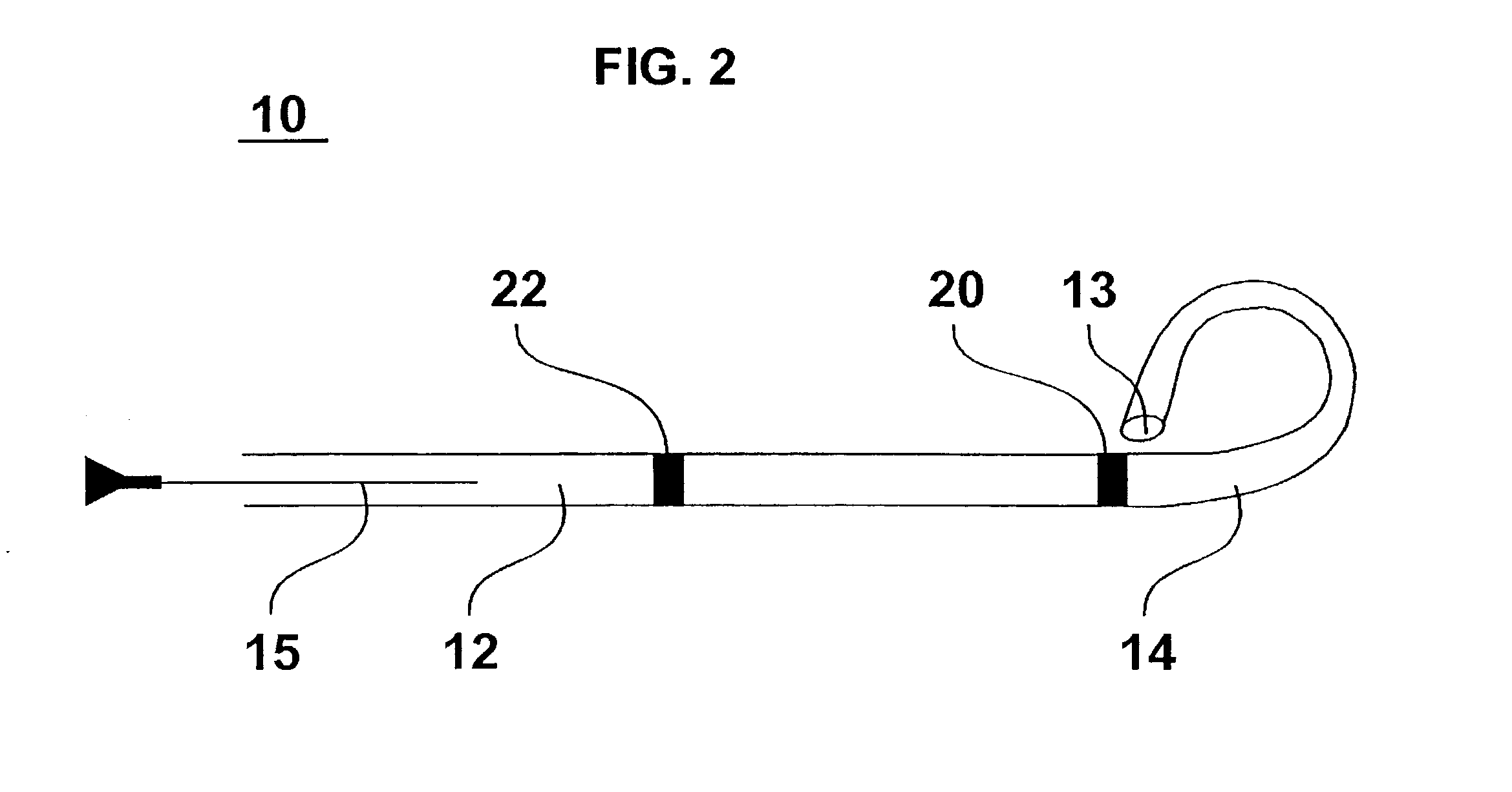
[0080]Referring now to FIG. 2, the electrical-anatomical imaging catheter-system 10 includes a lumen sheath 12 (about 3 mm in diameter) which has a pig tail distal end 14 to minimize motion artifacts inside the heart cavity. A guide wire 15 is advanced to a tip 13 to guide the sheath 12. The sheath 12 provides structural support for a coaxial multielectrode catheter-probe 16 (illustrated in FIG. 3A and FIG. 3B) that slides over the surface of the sheath 12, and records noncontact cavitary electrical signals (electrograms) from multiple directions. The sheath 12 also functions as a conduit for inserting an anatomical imaging catheter 18 (illustrated in FIG. 4) such as...


PUM


Abstract

A device for measuring parameters of human tissue includes a multielectrode catheter for taking multiple measurements of the electrical characteristics of the human tissue, a concentric tube catheter located inside the multielectrode catheter, for providing structural support to the multi-electrode catheter and for serving as a conduit for advancing or withdrawing the multielectrode catheter over its surface; and an imaging catheter located inside the concentric tube catheter for taking multiple measurements of anatomical characteristics of the human tissue.

Description


Claims


Application Information

Patent Timeline
Owner KHOURY DIRAR S
Why Eureka
Try Eureka