Sleeved bracing useful in the construction of earthquake resistant structures

Inactive Publication Date: 2007-03-13
COREBRACE LLC
View PDF19 Cites 35 Cited by
  • Summary
  • Abstract
  • Description
  • Claims
  • Application Information

AI Technical Summary

Benefits of technology

[0047]The present invention includes buckling restrained braces and systems in which such braces are used. The buckling restrained braces of the present invention may be used in seismic retrofits to increase the

Problems solved by technology

In use, the buckling restrained brace absorbs much of the potentially damaging loads that are a

Method used


Image

  • Sleeved bracing useful in the construction of earthquake resistant structures
  • Sleeved bracing useful in the construction of earthquake resistant structures
  • Sleeved bracing useful in the construction of earthquake resistant structures

Examples


Embodiment Construction

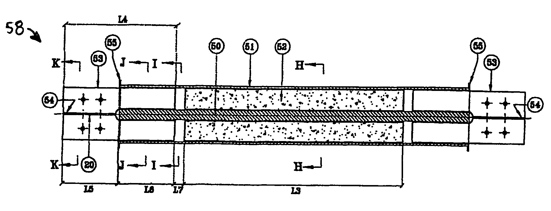
[0077]With reference to FIGS. 12a–12g, an exemplary embodiment of buckling restrained brace 58 according to the present invention is depicted. Buckling restrained brace 58 includes an elongate core rod 50, or “yielding core,” an elongate hollow sleeve 51 within which the core rod 50 is concentrically disposed, and a buckling constraining element, in this case a grout material 52, that fills a portion, shown as radial distance L3, of an annular gap between the core rod 50 and sleeve 51. An air gap remains between at least one surface of the core rod 50 and the grout material 52. The core rod 50 may be loosely disposed within and surrounded by the grout material 52.

[0078]In the depicted example, the core rod 50 has a solid round cross section, which may better resist buckling thereof than would a core rod 50 of rectangular cross section. Alternatively, the core rod 50 may have a cross-sectional shape, taken transverse to the length thereof, which is rectangular, square, or any other s...


PUM


Abstract

A buckling restrained brace includes an elongate, hollow sleeve, an elongate yielding core extending substantially through the length of the sleeve, and a buckling constraining element between the yielding core and the inner surface of the hollow sleeve and spaced apart from at least one surface of the yielding core, leaving a gap therebetween. The buckling constraining element may be spaced apart from and, thus, the gap may exist between two or more surfaces of the yielding core. Additionally, an inner sleeve, or liner, may be positioned between the buckling constraining element and the yielding core, with the liner being spaced apart from at least one surface of the yielding core. The buckling restrained brace is useful in absorbing loads, such as seismically induced loads, that are exerted upon a steel frame.

Description

CROSS-REFERENCE TO RELATED APPLICATIONS[0001]This application is a continuation-in-part of PCT / IN00 / 00087, with an international filing date of Sep. 12, 2000, for which the U.S. is a designated state.BACKGROUND OF RELATED ART[0002]1. Field of the Invention[0003]The present invention relates generally to sleeved braces, or “buckling restrained braces,” and methods for manufacturing the same. More specifically, the present invention relates to buckling restrained braces that include yielding core members that extend through an outer sleeve which contains a buckling constraining material, which yielding core members are laterally spaced apart from the buckling constraining material by way of an air gap. Among other purposes, the buckling restrained braces of the present invention are useful in the construction of earthquake resistant structures, such as earthquake resistant steel building frames.[0004]2. Background of Related Art[0005]In order to understand the importance of the buckli...

Claims


Application Information

Patent Timeline
IPC IPC(8): E04B1/98E04H9/02
CPCE04H9/02E04H9/028E04H9/0237
Inventor SRIDHARA, BENNE NARASIMHA MURTHY
Owner COREBRACE LLC
Why Eureka
Try Eureka