Convertible aircraft provided with two tilt fans on either side of the fuselage, and with a non-tilting fan inserted in the fuselage

a technology of a tilt fan and a fuselage, which is applied in the direction of vertical landing/taking off aircraft, rotorcraft, aircraft navigation control, etc., can solve the problems of reducing the cruising speed, requiring complex modifications either to the propulsion system or the engine, and requiring gas jets from the nozzles. to achieve the effect of increasing the payload of the aircra

Inactive Publication Date: 2007-03-13
EUROCOPTER
View PDF73 Cites 33 Cited by
  • Summary
  • Abstract
  • Description
  • Claims
  • Application Information

AI Technical Summary

Benefits of technology

[0010]In order to maintain equilibrium while hovering, three fans are quite sufficient to provide a support polygon. The weight saved by omitting a fourth fan enables the payload of the aircraft to be increased considerably.
[0014]In a second embodiment, the convertible aircraft has two main wings that are swept forward, and that are disposed on either side of the fuselage in the high position. Each of these wings is advantageously provided with double-slotted high-lift flaps. In addition, a tail fin and tail stabilizers enable the attitude of the aircraft to be controlled accurately. In addition, in this particular embodiment, the engines are arranged in the fuselage above the cabin, and they are fed with air via two distinct air inlets arranged in the top of the fuselage.

Problems solved by technology

The helicopter configuration enables stationary flight to be performed under satisfactory control, but that is to the detriment of cruising speed.
Nevertheless, the solutions that have been found so far have been of moderate efficiency and have required complex modifications either to propulsion systems or to engines.
In that configuration, each engine must be capable of operating both in a substantially horizontal position and also in a vertical position, and that raises numerous problems associated either with the engine or with the cabling or the hydraulic and fuel ducts that need to pass through a tilting pivot.
Furthermore, since the engines are generally turboengines, the gas jets from their nozzles have the drawback in helicopter mode of damaging the surface of take-off and landing areas.
However, using four tilt fans is particularly penalizing insofar as the aircraft must have sufficient engine power to be capable of driving all four tilt fans.
In addition, it goes without saying that the weight of the device is considerable, thereby correspondingly reducing the payload of the aircraft.
From those considerations, firstly it can be seen that the tilt rotor configuration is particularly difficult to implement and make suitable for industrial manufacture, because of the difficulties associated with tilting an engine.

Method used


Image

  • Convertible aircraft provided with two tilt fans on either side of the fuselage, and with a non-tilting fan inserted in the fuselage
  • Convertible aircraft provided with two tilt fans on either side of the fuselage, and with a non-tilting fan inserted in the fuselage
  • Convertible aircraft provided with two tilt fans on either side of the fuselage, and with a non-tilting fan inserted in the fuselage

Examples


first embodiment

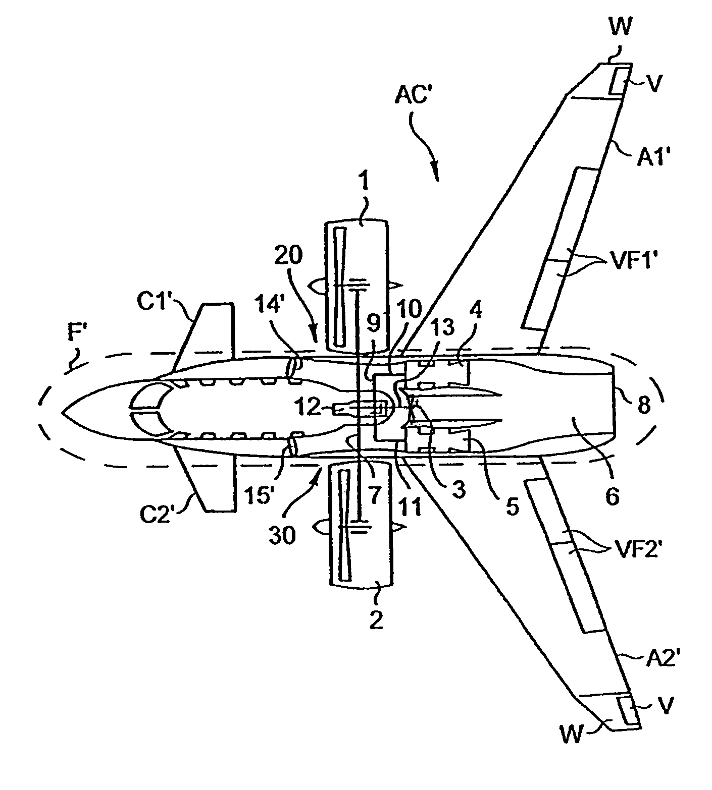
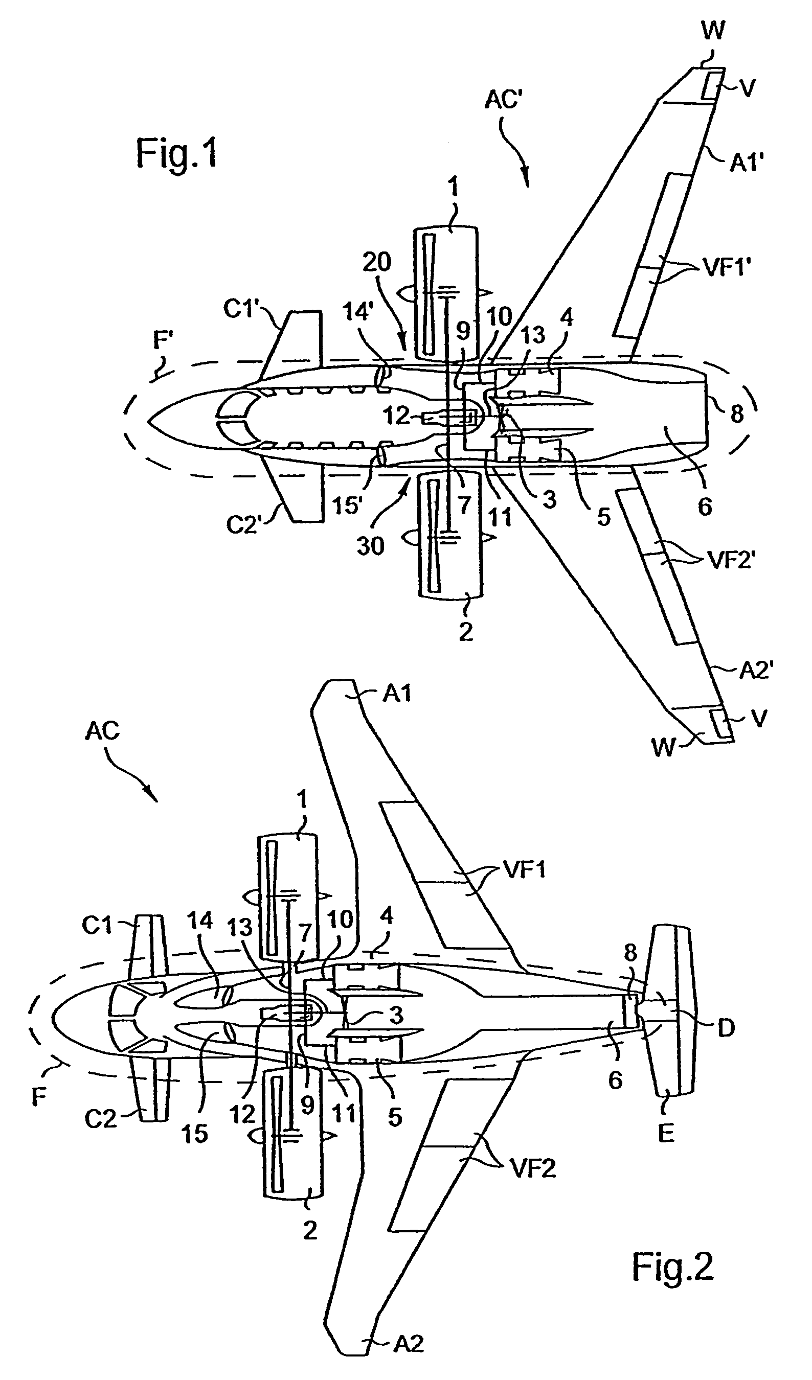
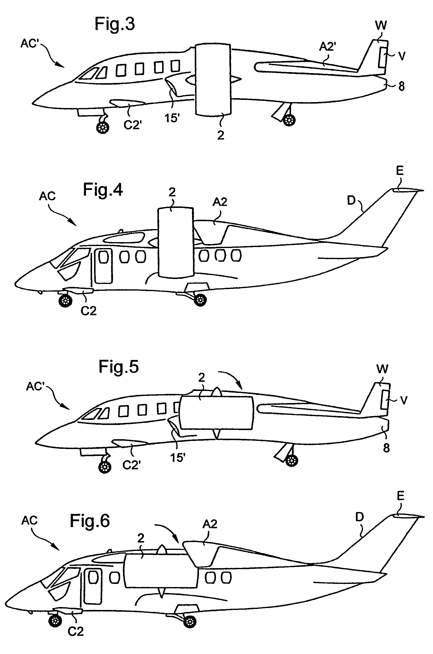
[0024]FIG. 1 shows a convertible aircraft AC′ constituting a This convertible aircraft AC′ has two engines 4, 5 inserted inside a fuselage F′, the engines being provided with respective drive shafts 10, 11. Two air inlets 14′ and 15′ are arranged in respective sides 20 and 30 of the fuselage F′ to feed air to the engines 4 and 5. The exhaust gases from the engines 4 and 5 are exhausted into a duct 6 of the fuselage F′.

second embodiment

[0025]FIG. 2 shows a convertible aircraft AC constituting a This convertible aircraft AC has two engines 4, 5 inserted inside a fuselage F, the engines being provided with respective drive shafts 10, 11. Two air inlets 14 and 15 formed in the top of the fuselage feed the engines 4 and 5 with air. The exhaust gases from these engines 4, 5 are exhausted into a duct 6 of the fuselage F.

[0026]In addition, having two engines for such convertible aircraft AC, AC′ presents the advantage of providing a high degree of safety, insofar as failure of a single engine will not significantly affect operation of the aircraft AC, AC′.

[0027]With reference to FIGS. 1 and 2, the drive shafts 10, 11 serve to rotate a single interconnection shaft 9 via two distinct gear sets.

[0028]A main gearbox 12 arranged on the interconnection shaft 9 acts, via a secondary transmission shaft 13, to transfer the power from the two engines 4, 5 to a non-tilting fan 3 fixed in a vertical position and inserted inside the...


PUM


Abstract

The present invention relates to a convertible aircraft provided with first and second tilt fans disposed on either side of the fuselage a little forward of the center of gravity of the convertible aircraft. In addition, the convertible aircraft includes, in remarkable manner, a non-tilting fan that is permanently in a vertical position and that is contained inside the fuselage.

Description

[0001]The present invention relates to a convertible aircraft provided with tilting ducted rotors, commonly referred to as “tilt fans”, the aircraft being capable of taking off and landing over very short distances, or even vertically.BACKGROUND OF THE INVENTION[0002]Numerous configurations have been attempted in the history of aviation to enable aircraft to take off and land vertically.[0003]The helicopter configuration enables stationary flight to be performed under satisfactory control, but that is to the detriment of cruising speed. Research has thus been undertaken to improve hovering control of airplanes. Nevertheless, the solutions that have been found so far have been of moderate efficiency and have required complex modifications either to propulsion systems or to engines.[0004]Document U.S. Pat. No. 5,054,716 discloses a convertible aircraft where each of the rotors together with its control and engine means constitutes a tilting assembly referred to as a “tilt rotor”. In t...

Claims


Application Information

Patent Timeline
Patent Type & Authority Patents(United States)
IPC IPC(8): B64C27/22B64C29/00
CPCB64C29/0033
Inventor MAGRE, ERIC
Owner EUROCOPTER
Why Eureka
Try Eureka