Vertebral arthrodesis equipment

a technology for arthrodesis equipment and vertebrae, which is applied in the field of vertebral arthrodesis equipment, can solve the problems of inconvenient one-piece members, inability to adapt to all situations, and inability to meet the needs of patients,

Inactive Publication Date: 2007-03-13
TAYLOR JEAN +3
View PDF7 Cites 83 Cited by
  • Summary
  • Abstract
  • Description
  • Claims
  • Application Information

AI Technical Summary

Benefits of technology

[0014]The head and spherical cavity thus form a ball and socket joint enabling multidirectional movement of one part of the cross-piece in relation to the other. The cross-piece according to the invention is thus able to accommodate all likely situations, in particular orientations of the shoring rods in different planes. When the appropriate relative position of the two parts of the cross-piece is determined, the nut is tightened on the thread until it comes against the wall of the bulging end and exerts some pressure thereon. This pressure creates a tension on the head relative to the bulging end and friction between them which enable the two parts of the cross-piece to be fixed to each other.
[0035]This attachment member thus facilitates the positioning of the equipment, and enables a gradual alignment of the shoring rods relative to the fixing plates.

Problems solved by technology

The one-piece members are inconvenient in that they cannot adapt to all situations, in particular not being able to accommodate all the different possible positions of the shoring rods.
However these cross-pieces only partially remedy the above mentioned problems.
Furthermore, the attachment members for the shoring rods of existing equipment do not perform satisfactorily.
These members are either relatively complex and difficult to manufacture, or are awkward and raise the cross-pieces above the shoring rods to such a degree that they become noticeable under the skin, or leave doubts as to the long term durability of the assembly.
Furthermore, the attachment of existing equipments to the sacrum is relatively problematic, due to the lack of an anchoring member well adapted to fixing the shoring rods to the sacrum.

Method used


Image

  • Vertebral arthrodesis equipment
  • Vertebral arthrodesis equipment
  • Vertebral arthrodesis equipment

Examples


Embodiment Construction

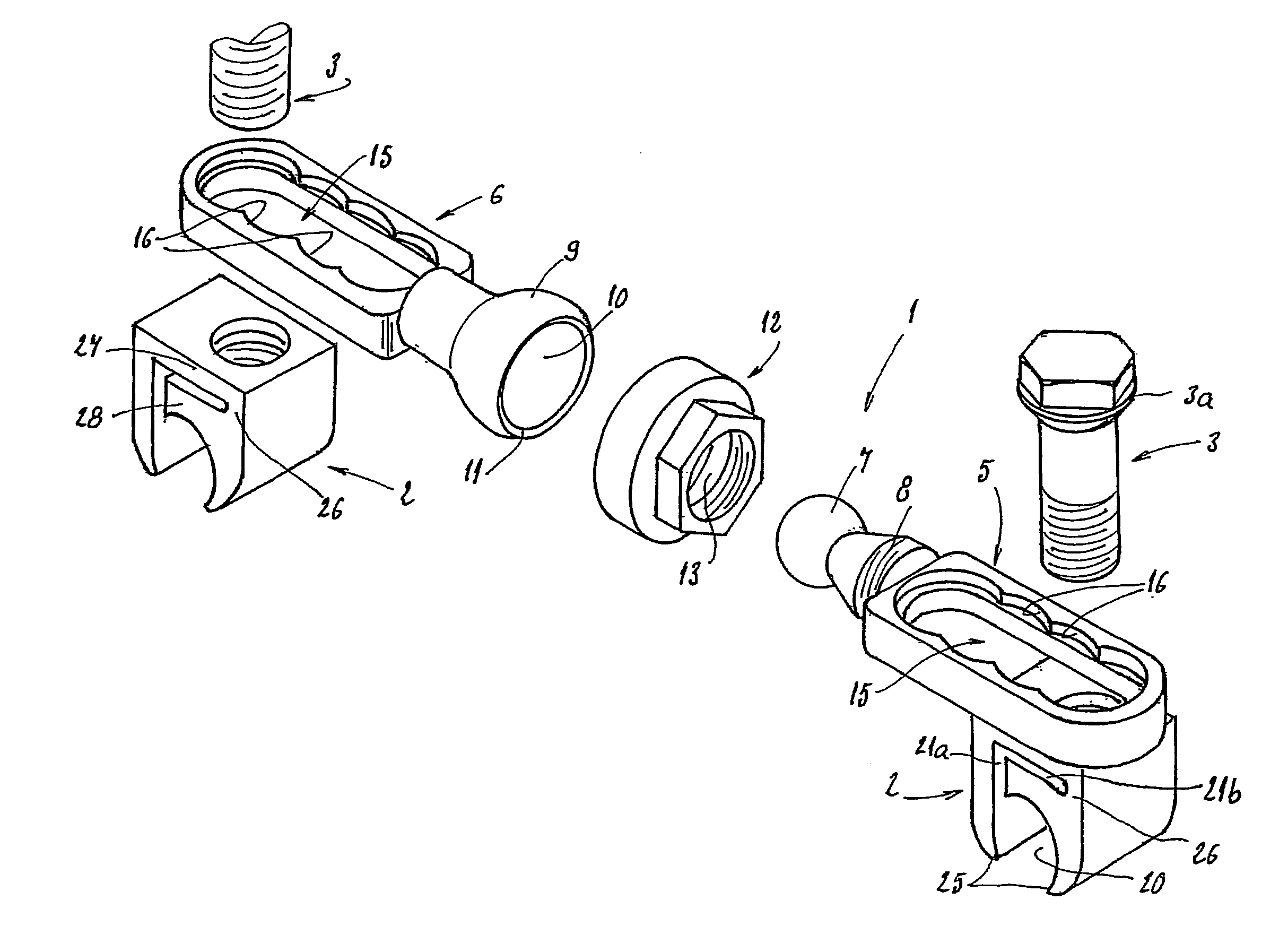
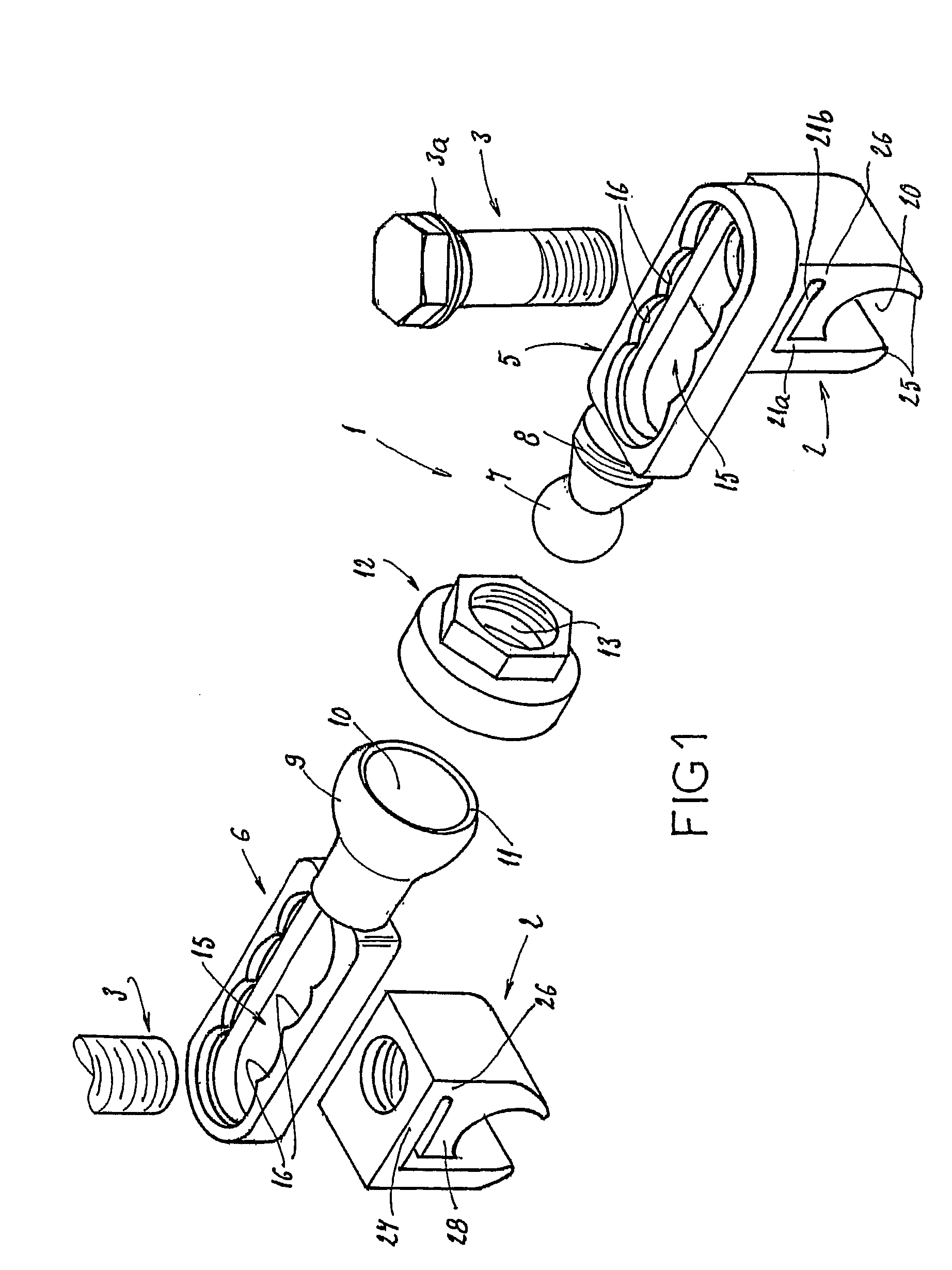
[0041]FIG. 1 shows a cross-piece 1, the attachment pieces 2, and the screws 3, that are part of the vertebral arthrodesis equipment.

[0042]This equipment also includes two shoring rods to be placed parallel to each other on either side of the vertebrae to be treated, and anchoring members for attaching these rods to the vertebrae, such as hooks or pedicle screws. These rods and anchoring members are well-known and are therefore not fully described.

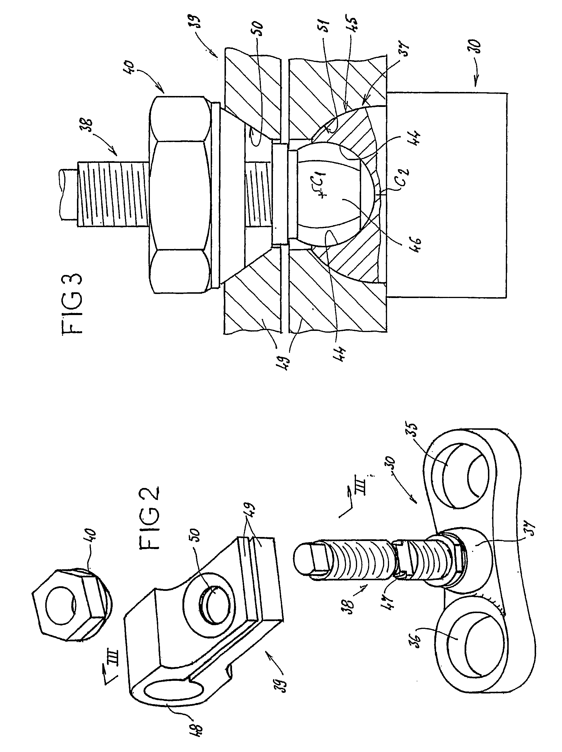
[0043]As FIG. 1 shows, the cross-piece 1 is in two parts 5 and 6. Part 5 has a spherical head 7 at its extremity that is intended to be connected to part 6, and a thread 8 adjacent to the head 7. Part 6 has a spherical bulging end 10 that receives the head 7 with the possibility of movement of this head 7 within the cavity 10. The inner surface of the cavity 10 fits around the head 7 in such a way as to retain the head within the cavity 10.

[0044]The cross-piece 1 also includes a nut 12 mounted on the part 5, that is able to co-operate with ...


PUM


Abstract

The invention concerns an equipment comprising two shoring rods, members for anchoring said two rods to the vertebrae, at least a crosspiece (1) in two parts (5, 6) and members (2) assembling said crosspiece (1) to the shoring rods. The invention is characterised in that one of the crosspiece parts (5) comprises a spherical head (7) and a thread (8) adjacent to said head (7); the other crosspiece part (6) comprises a spherical bulging end (9), defining internally a spherical cavity (10) adapted to receive said head (7), and each crosspiece (1) comprises a nut (12) designed to co-operate with said thread (8), including further a spherical seat (13) with a shape matching that of the wall (11) delimiting the cavity (10). The invention also concerns plates (30for anchoring the equipment to the sacrum.

Description

FIELD OF THE INVENTION[0001]The present invention relates to a vertebral arthrodesis equipment.DESCRIPTION OF THE RELATED ART[0002]Usually such equipment includes two parallel shoring rods attached to either side of the vertebrae and anchoring members of these rods to the vertebrae, such as hooks or pedicule screws. These equipment may also include cross-pieces running between the two rods in order to keep them in place.[0003]These cross-pieces in some cases consist of simple one-piece members, linked to the support rods with an appropriate attachment member. The one-piece members are inconvenient in that they cannot adapt to all situations, in particular not being able to accommodate all the different possible positions of the shoring rods. Especially, the separation between the support rods may vary from one place to another, or the support rods may be oriented in different planes.[0004]Two-part cross-pieces have been developed that can pivot in one plane in relation to each other...

Claims


Application Information

Patent Timeline
Patent Type & Authority Patents(United States)
IPC IPC(8): A61B17/56A61B17/70A61B90/00
CPCA61B17/7055A61B17/7052A61B17/701A61B17/7044A61B2019/307A61B2090/037
Inventor TAYLOR, JEANVILLARET, BERNARDPARISINI, PATRIZIOCLEMENT, JEAN-LUC
Owner TAYLOR JEAN
Why Eureka
Try Eureka