
Color conversion with hue straightening using multiple look-up tables and interpolation

a color conversion and hue straightening technology, applied in the field of color conversion for digital imagery, can solve the problems of insufficient flexibility of simple ucr/gcr technique, inability to fully utilize the color gamut of the additional k colorant, and inability to implement in real-tim

Active Publication Date: 2007-03-13
SHARP KK
View PDF39 Cites 38 Cited by
  • Summary
  • Abstract
  • Description
  • Claims
  • Application Information

AI Technical Summary

Benefits of technology

[0043]Another object of the invention is to provide a method of maintaining a neutral gray scale, accurate hue angles, and proper perceptual spacing in color ramps from black to primary and black to secondary colors.

Problems solved by technology

These techniques are simple to implement, but cannot fully utilize the color gamut possible with the additional K colorant.
Other brute-force techniques that search the entire CMYK signal space for desirable combinations can produce good results but are unsuitable for real-time implementation.
The simple UCR / GCR technique mentioned above does not provide enough flexibility to select a “best” CMYK combination to reproduce a specified color.
The color gamut of the resulting RGB printer is also reduced, due to the inability of the simple technique to use certain combinations of CMYK values.
However, constructing a printer target that extensively samples the entire printer CMYK space, measures the printed target in a colorimetric space, such as CIELAB, and interpolates to find all possible CMYK signals for each in-gamut color specified in the colorimetric space is a computationally intensive, “brute force” method.
Therefore, these methods alone are not sufficient for modeling a CMYK printer as an RGB printer, although they are useful in creating a 3-D color LUT that converts colors in a colorimetric space directly to printer CMYK signals.
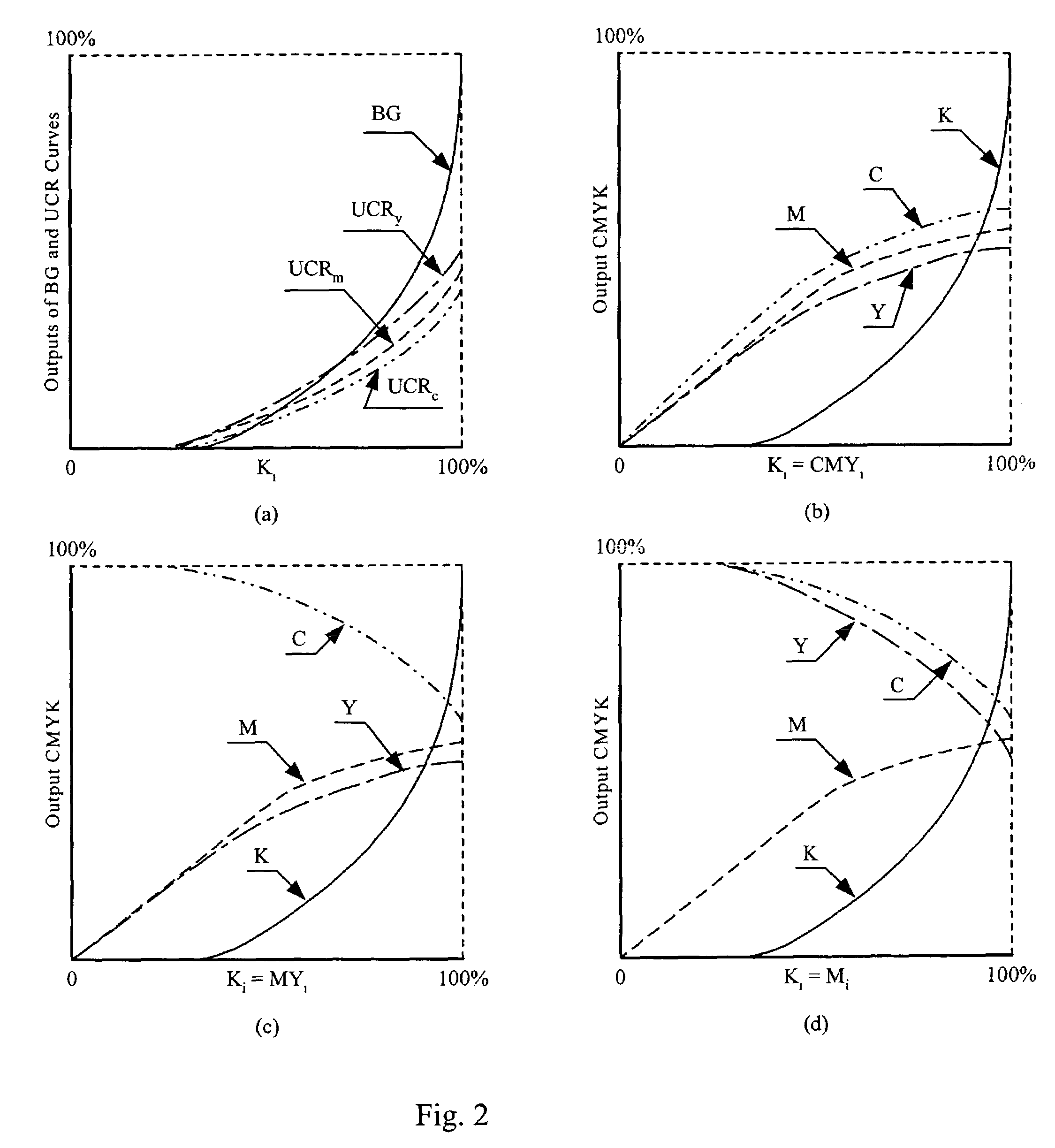
The problem to be solved is how to determine the amount of black colorant to be used based on an RGB or CMY input, and how to adjust the other colorants once black colorant is introduced.

Method used


Image

  • Color conversion with hue straightening using multiple look-up tables and interpolation
  • Color conversion with hue straightening using multiple look-up tables and interpolation
  • Color conversion with hue straightening using multiple look-up tables and interpolation

Examples


Embodiment Construction

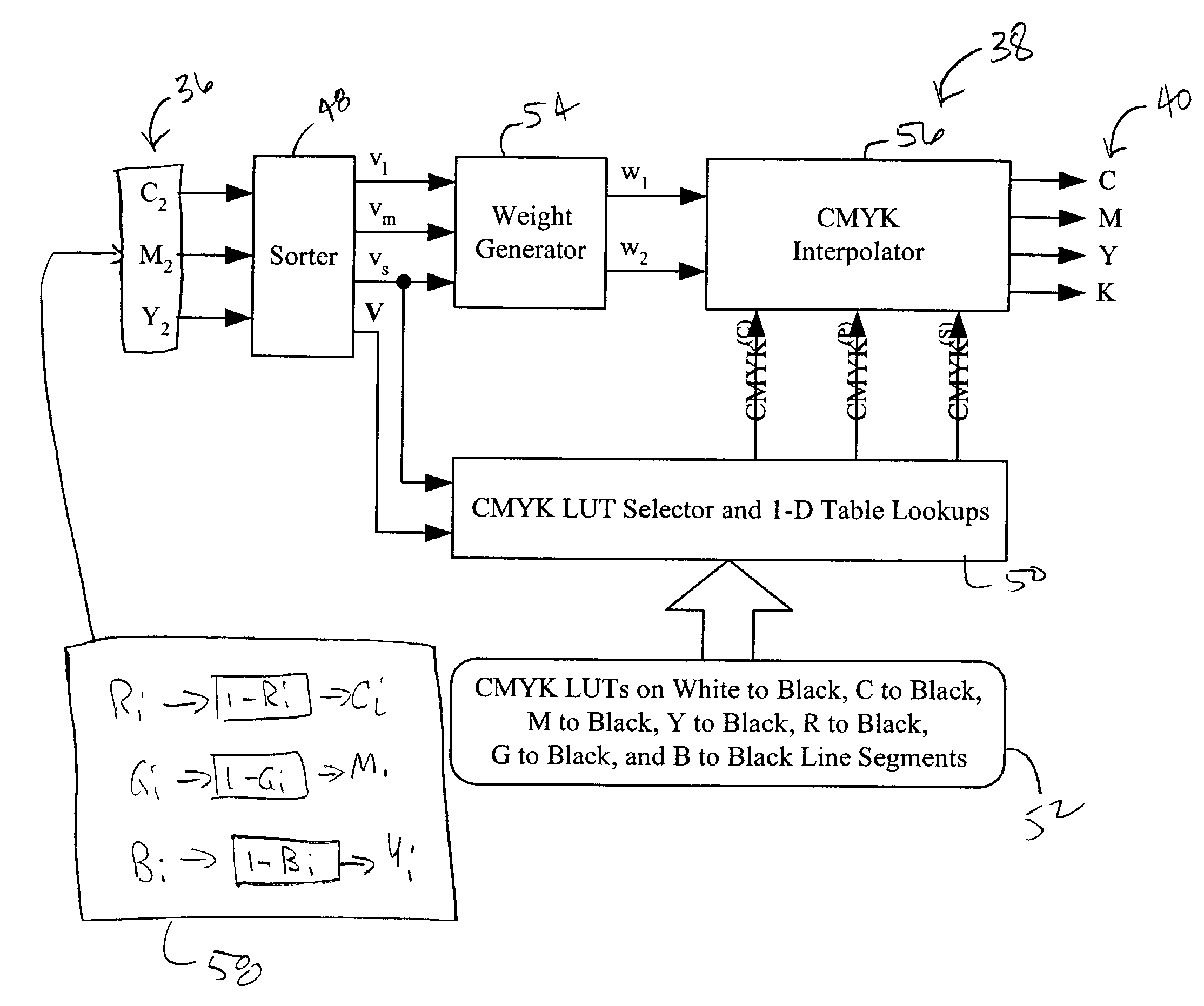
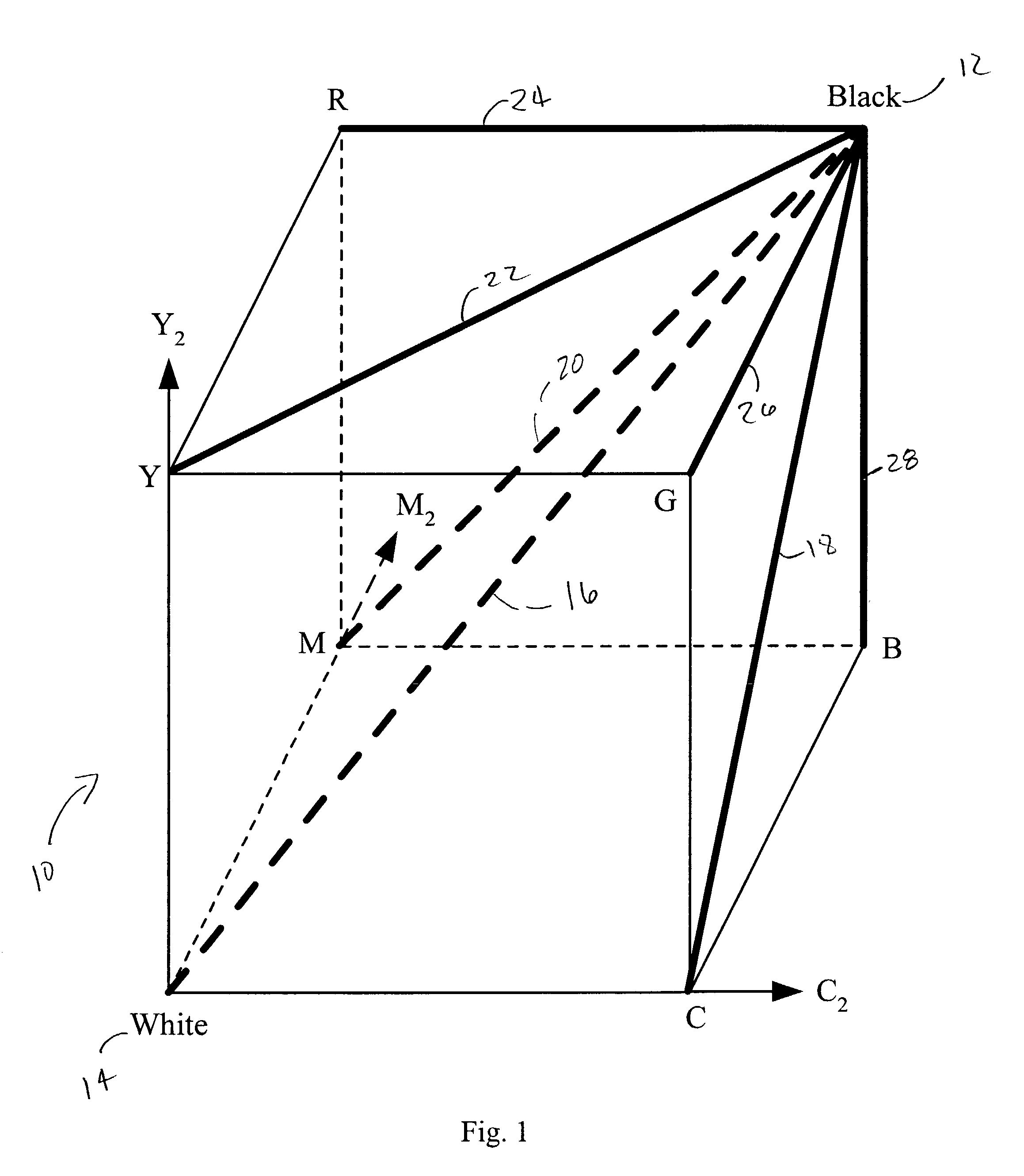
[0059]The method of the invention includes a flexible computational structure for converting RGB (Red Green Blue) or CMY (Cyan Magenta Yellow) signals to CMYK (Cyan Magenta Yellow black) signals. This structure, which may be viewed as an extension of the traditional Under-Color Removal (UCR) and Gray Component Replacement (GCR) techniques, uses multiple sets of 1-D CMYK look-up tables (LUTs) to control the CMYK colorant usage. The LUTs are strategically placed on the center diagonal and boundaries of the input signal color cube. By properly designing these LUTs, a model for RGB-to-CMYK conversion is obtained which utilizes most of the available CMYK gamut and also corrects certain non-ideal device behaviors, such as hue shifts along lines from the pure colors to black or white, which may result from downstream halftoning and page marking processes. For example, the LUTs may be constrained so that the hue angles in ramps from pure colors to white or black will remain constant.

[0060]T...


PUM


Abstract

A method of color conversion includes providing a first color domain input signal set having plural input signals; sorting the input signals of the first color domain input signal set according to signal intensity; designing and generating plural 1-D look-up table sets for color polyhedrons; selecting a set of look-up tables for use with a specific color polyhedron, wherein said selecting is a function of a section of the polyhedron determined as a function of the input signal set; looking up values in the look-up table set as a function of the input signal set; generating weights as a function of the sorted signal intensities; and interpolating the output from the selected look-up tables as a function of the selected look-up table and the generated weights to produce a color domain signal set which is converted to a desired color domain signal set.

Description

RELATED APPLICATIONS[0001]This application is related to U.S. patent application Ser. No. 09 / 741,458, filed Dec. 19, 2000, for Black Generation Method for CMYK Color Printers Using Multiple Lookup Tables and Interpolation, and claims priority from U.S. Provisional Patent Ser. No. 60 / 324,862 for Color Conversion with Hue Straightening using Multiple Lookup Tables and Interpolation, filed Sep. 25, 2001, and U.S. Provisional Patent Ser. No.: 60 / 390,283 for Color Conversion with Hue Straightening using Multiple Lookup Tables and Interpolation, filed Oct. 23, 2001.FIELD OF THE INVENTION[0002]This invention is in the field of color conversion for digital imagery, and pertains specifically to a method of converting RGB input signals into printer CMYK signals for printers having four colorants: cyan (C), magenta (M), yellow (Y), and black (K), and to general color conversion methods, such as color correction for LCD displays.BACKGROUND OF THE INVENTION[0003]Many color-printing devices use c...

Claims


Application Information

Patent Timeline
IPC IPC(8): G06F15/00G06K15/02H04N1/60
CPCH04N1/6025G06K15/02G06F15/00
Inventor DALRYMPLE, JOHN CHARLESCHANG, JAMES ZHIXININOUE, CHIZU
Owner SHARP KK
Learn More