Fluidic control system

a technology of control system and fluid power, which is applied in the direction of service pipe system, water main, gas/liquid distribution and storage, etc., can solve the problem that no conclusions can be drawn about the operation sta

Inactive Publication Date: 2007-03-20
FESTO AG & CO KG
View PDF12 Cites 23 Cited by
  • Summary
  • Abstract
  • Description
  • Claims
  • Application Information

AI Technical Summary

Benefits of technology

[0015]Certain states of a principal valve, for example the switching position of the valve member, may be detected, using suitable sensor means, without any direct access to the internal space of the respective principal valve. This applies for example for contact-less interrogation of the switching position, more particularly using inductive proximity sensors. If however for example an optical monitoring of switching position or the detection of the fluid pressures

Problems solved by technology

In all cases there is however the disadvantage that from the switching state of the val

Method used


Image

  • Fluidic control system
  • Fluidic control system
  • Fluidic control system

Examples


Embodiment Construction

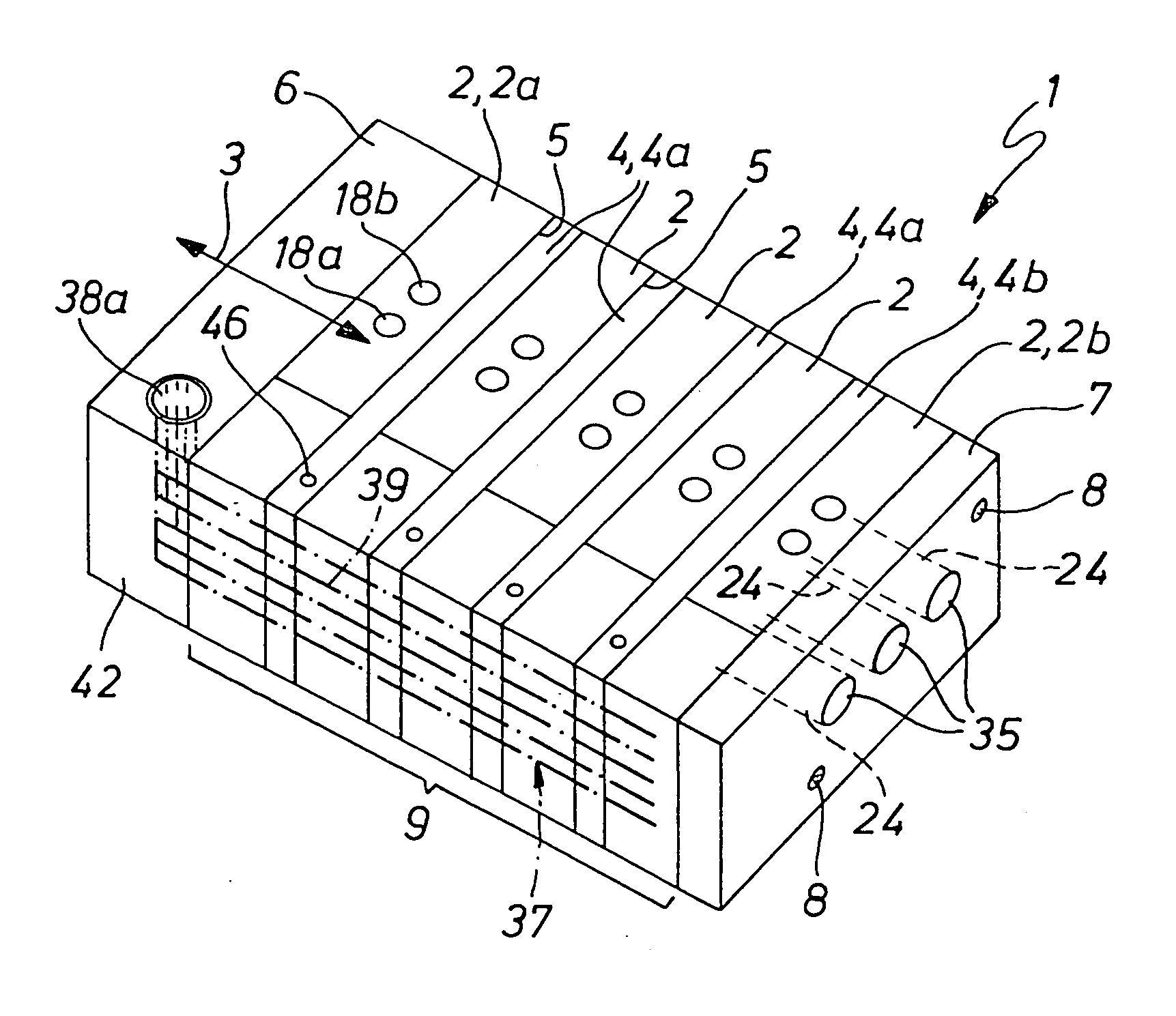
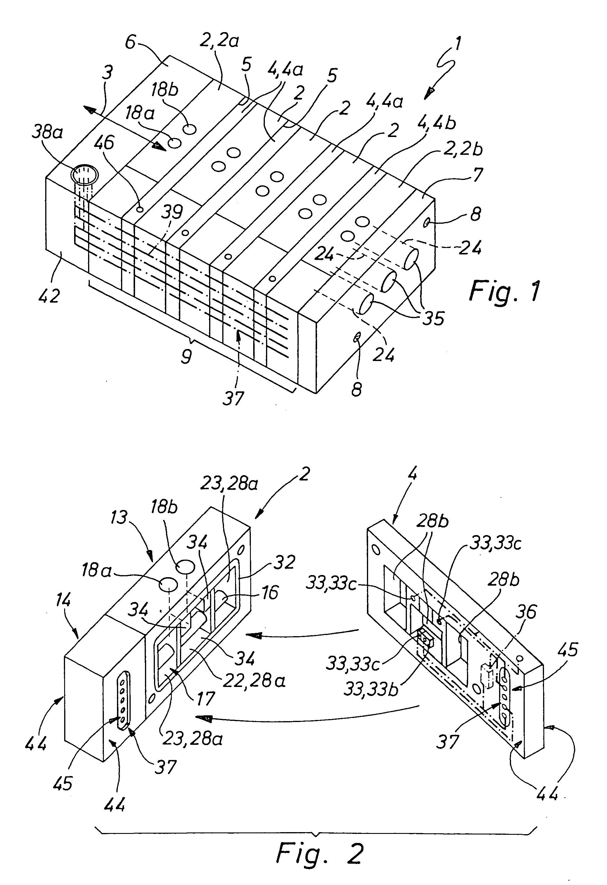
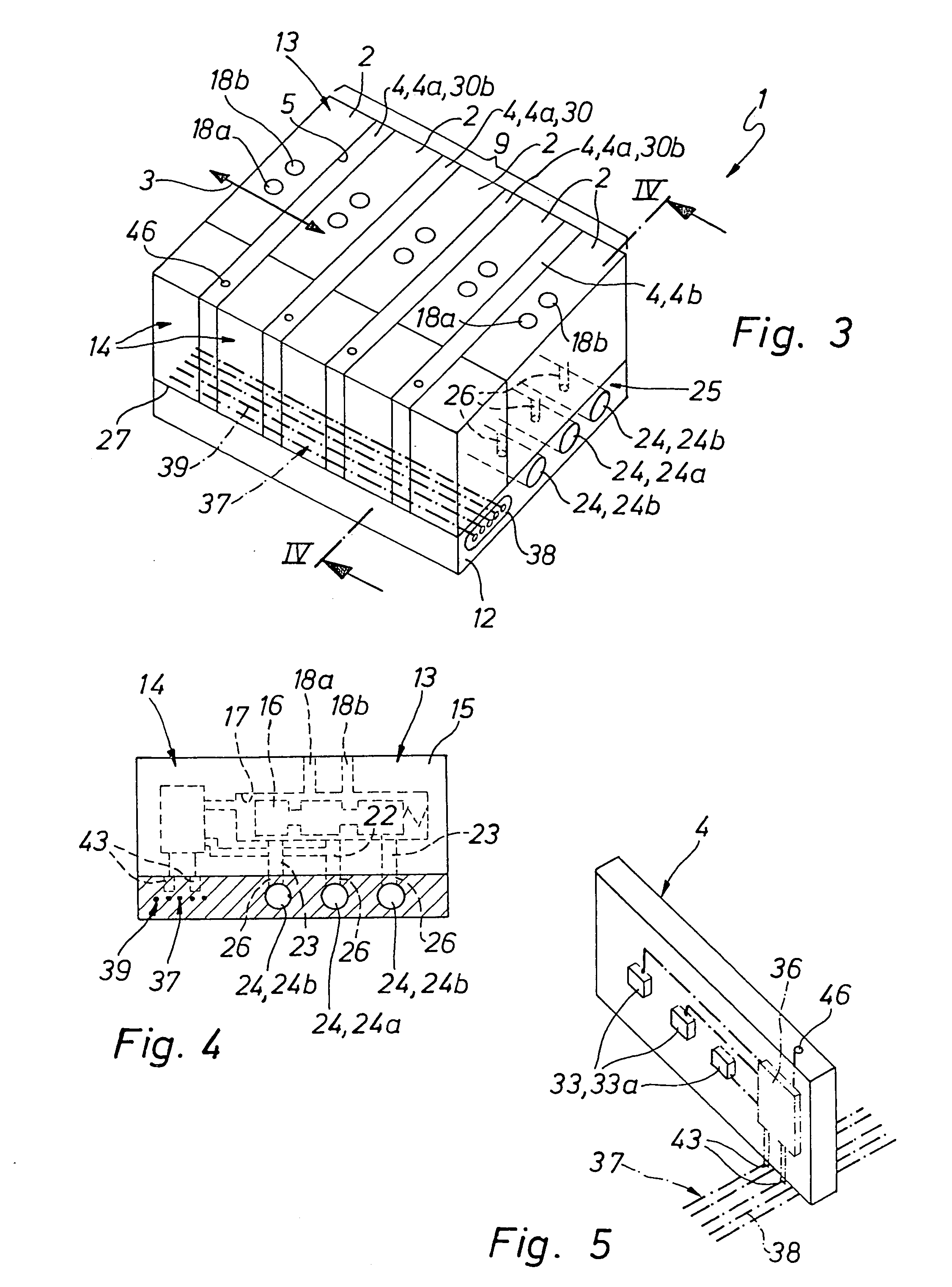
[0022]FIGS. 1 and 2 on the one hand and FIGS. 3 through 5 on the other hand show two different working examples of the fluid power controller device 1 in accordance with the invention, which is able to be employed for the operation of a machine, a group of machines or individual tools, the means to, be controlled being operated by fluid force, more particularly pneumatically. In case of need the controller devices 1 may be additionally provided with components, not depicted in detail, which render possible the operation of electrical instrumentalities.

[0023]The illustrated controller devices 1 have the feature in common that same comprise a plurality of valve modules 2, which are arranged in a row direction 3 indicated by a double arrow and are collected together as an array-like unit 9.

[0024]As further components of this array-like unit 9 there are several preferably disk-like or plate-like flat diagnostic modules 4, of which respectively one is placed between two valve modules 2 f...


PUM


Abstract

A fluid power controller device comprises a plurality of valve modules arranged sequentially in a row direction and collected together as an array-like unit, such modules comprising respectively a principal valve having at least one moving valve member and at least one electrically operated valve drive for the principal valve. At least two of the valve modules placed sequentially in the row direction are spaced from each other with the formation of an intermediate space. In such intermediate space a diagnostic module is placed for the detection of at least one operational state of one or both principal valves.

Description

[0001]This application is a National Phase application of International Application No. PCT / EP2003 / 013061, filed Nov. 21, 2003, which claims priority based on German patent Application No. 202 19 497.3, filed Dec. 17, 2002, which are incorporated herein by reference.FIELD OF THE INVENTION[0002]The invention relates to a fluid power controller device comprising valve modules arranged in sequence in a row direction and collected together as an array-like unit, such modules each including a principal valve fitted with at least one moving valve member and at least one electrically operated valve drive for the principal valve.BACKGROUND OF THE INVENTION[0003]The German patent publication 29,909,529 U1 discloses various forms of such a controller device, several valve modules being collected together in each case to constitute an array-like unit and such unit being either designed to be self-supporting or being placed on a plate-like module carrier. The valve modules each comprise a princ...

Claims


Application Information

Patent Timeline
IPC IPC(8): F16K11/22F15B13/00F15B13/04F15B13/08F15B19/00
CPCF15B13/0814F15B13/0828F15B13/0839F15B13/0857F15B13/086F15B13/0867F15B13/0875F15B13/0889F15B19/00F15B13/0864F15B2013/0409Y10T137/87885Y10T137/8242Y10T137/8326Y10T137/8225
Inventor BERNER, MICHAELBOGDANOWICZ, GRZEGORZ
Owner FESTO AG & CO KG
Why Eureka
Try Eureka