
Hot fillable container

a technology of plastic containers and hot filling, which is applied in the field of plastic containers, can solve the problems of increasing the cost of the product, increasing the risk of container failure during storage or handling, and becoming prohibitive in cost, and achieve the effect of decreasing the volume of the container

Active Publication Date: 2007-03-20
AMCOR RIGID PLASICS USA LLC
View PDF21 Cites 52 Cited by
  • Summary
  • Abstract
  • Description
  • Claims
  • Application Information

AI Technical Summary

Benefits of technology

The invention is a plastic container that can maintain its shape and integrity after being hot filled and cooled. It has a special design that allows it to distort inwardly in a controlled manner, allowing it to absorb negative pressure or vacuum without getting bent or deformed. This design is achieved through flex panels and columns in the sidewall of the container that move to adjust to the vacuum forces inside. The benefits of this design are that it ensures the container remains stable and secure, even when it is filled and cooled.

Problems solved by technology

Nevertheless, because glass is fragile, easily breakable and heavy, it has become cost prohibitative, due to the high number of bottle breaks during handling.
Moreover, as a result of breakage preventive measures and weight, the transportation expenses associated with glass greatly increases the cost of the product.
However, a container that is used for hot fill applications is subject to additional mechanical stresses on the container that result in the container being more likely to fail during storage or handling.
For example, it has been found that the thin sidewalls of the container deform or collapse as the container is being filled with hot fluids.
This product shrinkage phenomenon results in the creation of a negative pressure or vacuum within the container.
If not controlled or otherwise accommodated, these negative pressures or vacuums result in deformation of the container which leads to either an aesthetically unacceptable container or one which is unstable.
Due to the relative high cost of PET material, even slight increases in the weight of the material of the container will result in an excessive increase in its cost, making it less competitive in relation to the glass bottle, thereby resulting in the infeasibility of such a solution to the problem.
One drawback with the use of nitrogen dosing technology however is that the maximum line speeds achievable with the current technology is limited to roughly 200 containers per minute.
Such slower line speeds are seldom acceptable.
Additionally, the dosing consistency is not yet at a technological level to achieve efficient operations.
Minimizing head space requires more precision during filling, again resulting in slower line speeds.
Reducing fill temperatures limits the type of commodity capable of being used and thus is equally disadvantageous.
Traditionally, these paneled areas have been semi-rigid by design, unable to accommodate the high levels of negative pressure or vacuum currently generated, particularly in lightweight containers.
While commercially successful, the inward flexing of the rectangular panels caused by the hot fill vacuum creates high stress points at the top and bottom edges of the pressure panels, especially at the upper and lower corners of the panels.
These stress points weaken the portions of the sidewall near the edges of the panels, allowing the sidewall to collapse inwardly during handling of the container or when containers are stacked together.

Method used


Image

  • Hot fillable container
  • Hot fillable container
  • Hot fillable container

Examples


Embodiment Construction

[0021]The following description of the preferred embodiment is merely exemplary in nature, and is in no way intended to limit the invention or its application or uses.

[0022]As discussed above, to accommodate vacuum forces during cooling of the contents within a hot fill or heat set container, containers have been provided with a series of vacuum panels around their sidewalls. Traditionally, these vacuum panels have been semi-rigid and incapable of preventing unwanted distortion elsewhere in the container, particularly in lightweight containers.

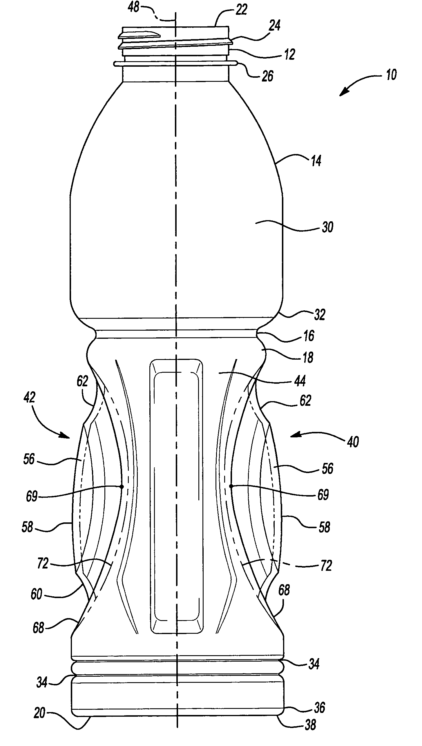
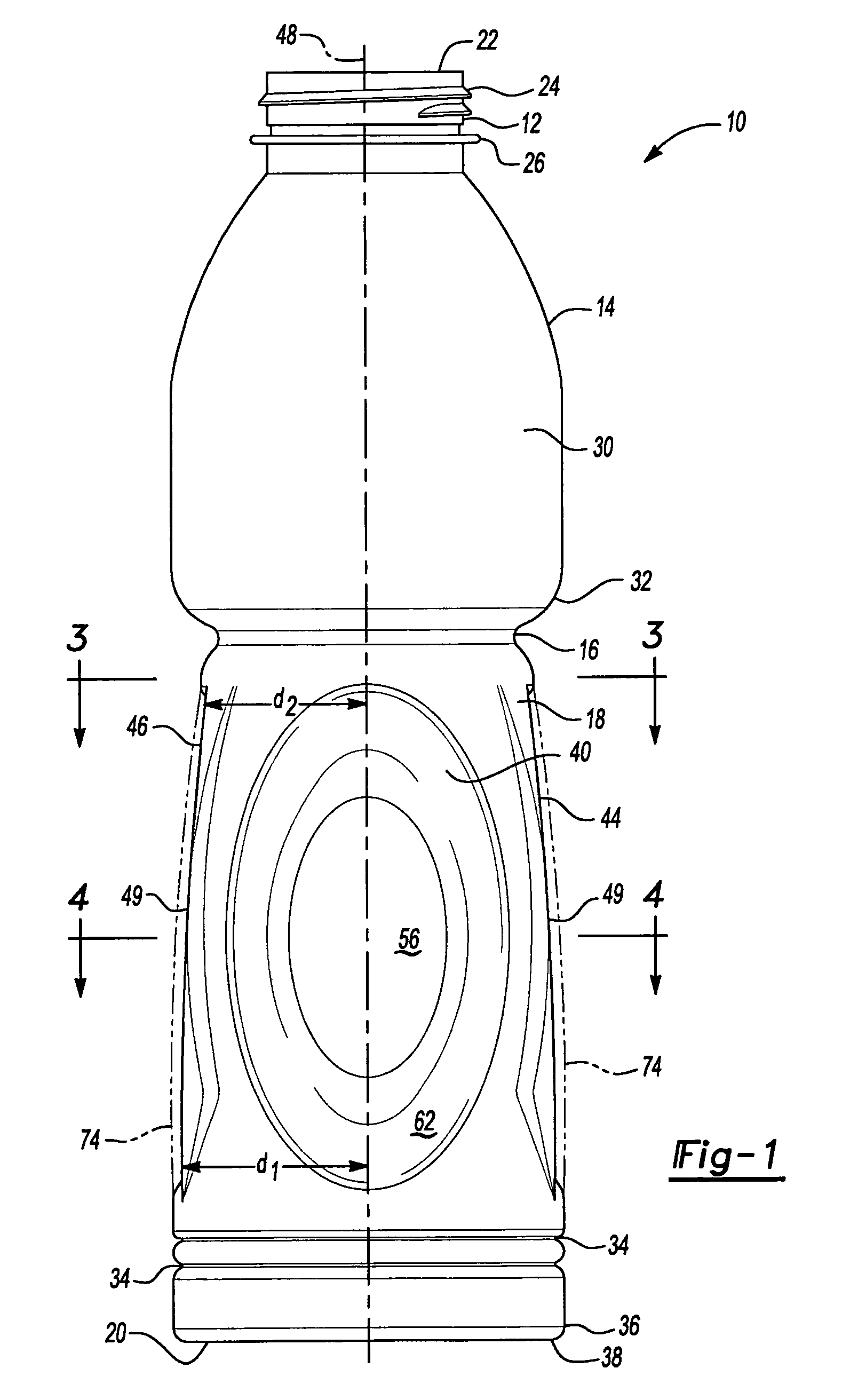
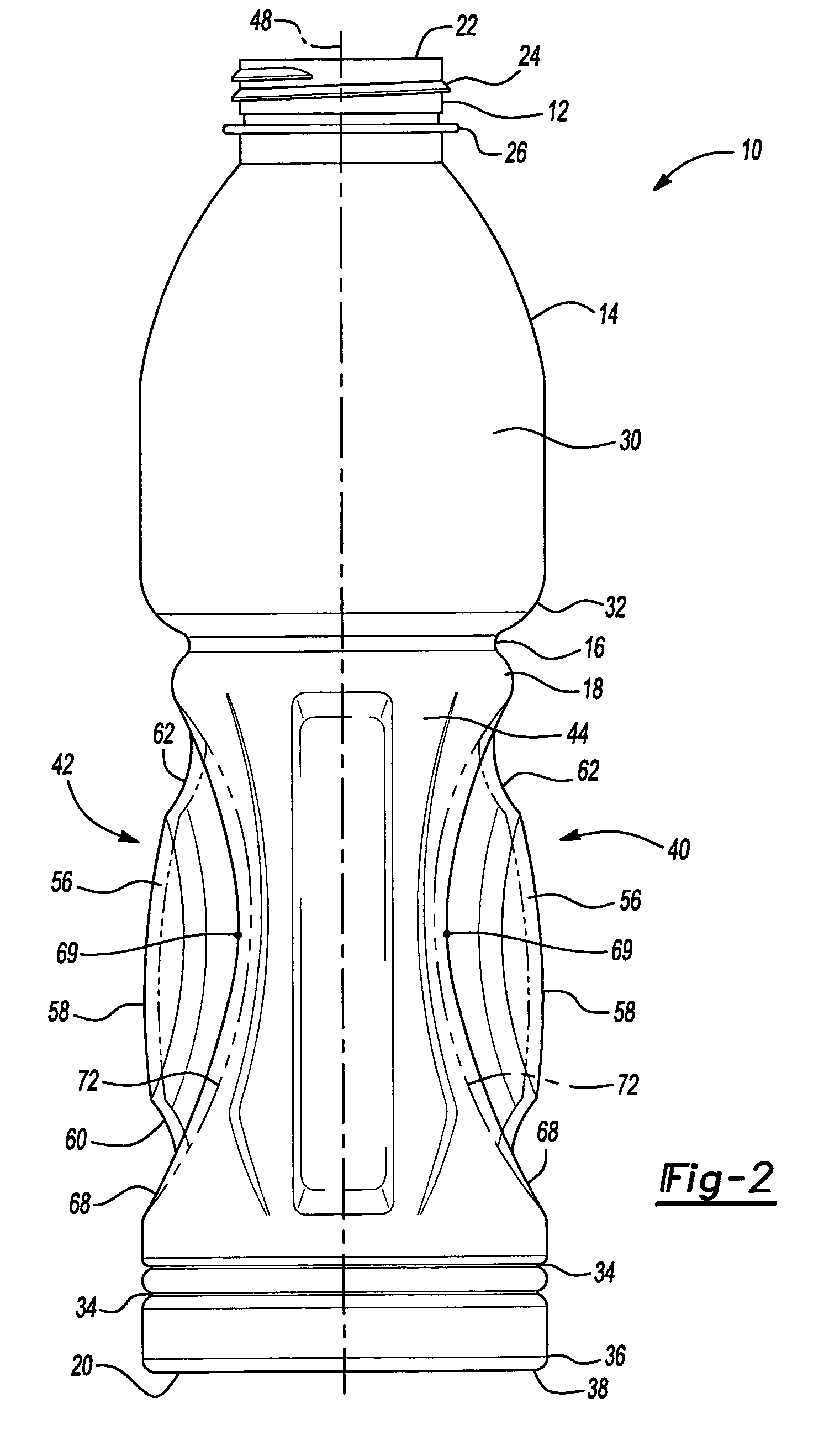
[0023]Referring now to the drawings, there is depicted a hot fillable, blow molded plastic container 10 embodying the principles and concepts of the present invention. The container 10 of the present invention illustrated in FIGS. 1–6 is particularly suited for hot fill packaging of product, typically a liquid or beverage, while the product is in a heated state. The container 10 can be filled by automated, high speed, hot fill equipment known ...


PUM


Abstract

A hot fill, blow molded plastic container adapted for vacuum pressure absorption having a pair of flex panels and a pair of columns. The flex panels being defined in at least part by a central portion and a perimeter wall portion adjacent to and generally surrounding the central portion. The flex panels being movable to accommodate internal thermally induced volumetric and pressure variations in the container resulting from heating and cooling of its contents.

Description

TECHNICAL FIELD OF THE INVENTION[0001]This invention generally relates to plastic containers that retain a commodity. More specifically, this invention relates to a hot fillable, blow molded plastic container having a novel construction allowing for significant absorption of vacuum pressures and accommodating reductions in product volume during cooling and capping of a hot filled product while resisting undesirable and unwanted deformation.BACKGROUND OF THE INVENTION[0002]Traditionally, containers used for the storage of products for human consumption were made of glass. Typical desirable glass characteristics include transparency, indeformability and perfect label fixation. Nevertheless, because glass is fragile, easily breakable and heavy, it has become cost prohibitative, due to the high number of bottle breaks during handling. Moreover, as a result of breakage preventive measures and weight, the transportation expenses associated with glass greatly increases the cost of the prod...

Claims


Application Information

Patent Timeline
Patent Type & Authority Patents(United States)
IPC IPC(8): B65D1/40B65D23/10B65D1/02B65D79/00
CPCB65D1/0223B65D79/005B65D2501/0027B65D2501/0018B65D79/0084
Inventor DEEMER, DAVID A.MOURAD, HASSAN
Owner AMCOR RIGID PLASICS USA LLC
Learn More