
Variable spring resistance assembly and method

a technology of springs and assemblies, applied in the field of variable springs, can solve the problems of affecting the performance of the spring, the spring snapping is time-consuming and inconvenient, and the loss of the spring from the grip of the person, so as to improve the speed and convenience, and eliminate the effect of annoyan

Inactive Publication Date: 2007-03-20
KELLION CORP
View PDF20 Cites 17 Cited by
  • Summary
  • Abstract
  • Description
  • Claims
  • Application Information

AI Technical Summary

Benefits of technology

[0003]This invention solves the problem of connecting and disconnecting springs, bungie cords, and similar elastically extendable elements by providing a grouping of these elements, all in a connected condition, arranged so that a desired number of elements to be deployed for a resistance can be easily selected. The invention thus aims at packaging a collection of springs or resistance elements that need not be connected or unconnected during use, but also can be selected or specified in different numbers to provide a desired resistance. The selectable combination of spring resistances offered by the invention thereby improves speed and convenience and eliminates the annoyance of having to connect and disconnect springs to adjust an exercising resistance.

Problems solved by technology

Springs not in use have to be parked out of the way, and the hooking and unhooking of tension springs is time consuming and inconvenient.
The connecting and disconnecting of springs can also result in springs snapping lose from a person's grip, and can cause minor injuries such as bruised or pinched fingers.

Method used


Image

  • Variable spring resistance assembly and method
  • Variable spring resistance assembly and method
  • Variable spring resistance assembly and method

Examples


Embodiment Construction

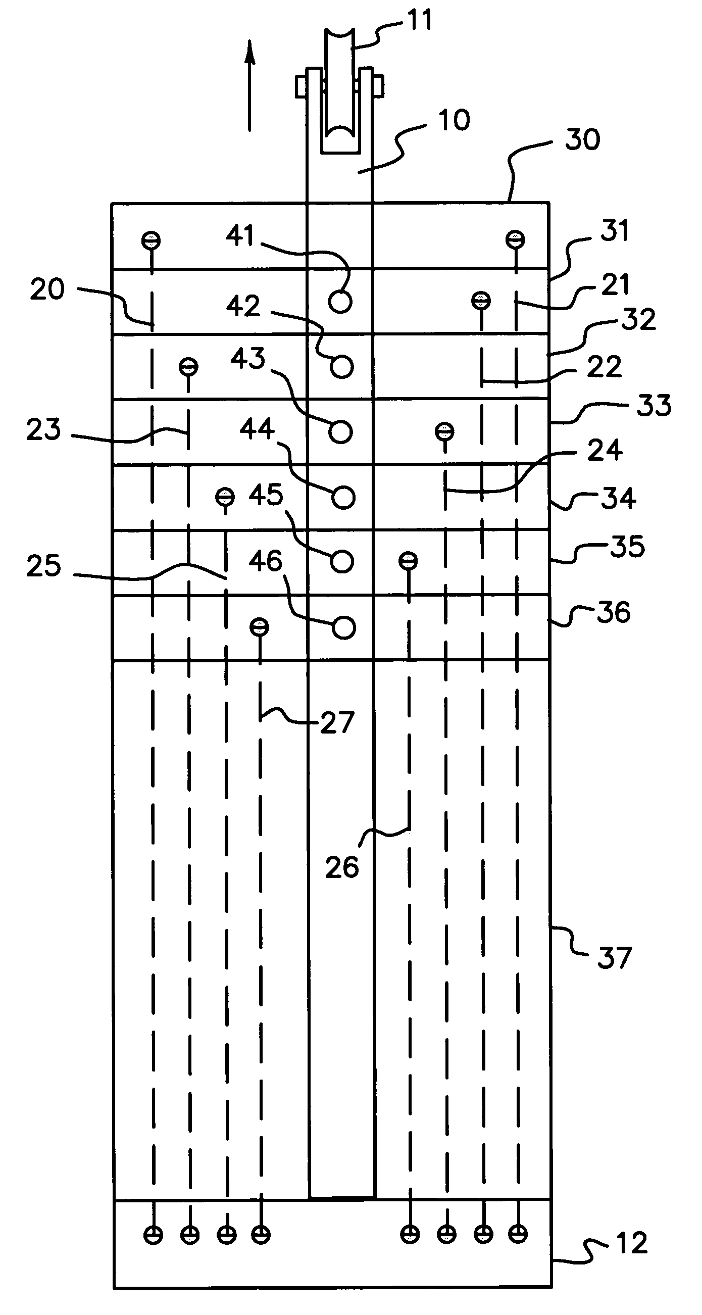
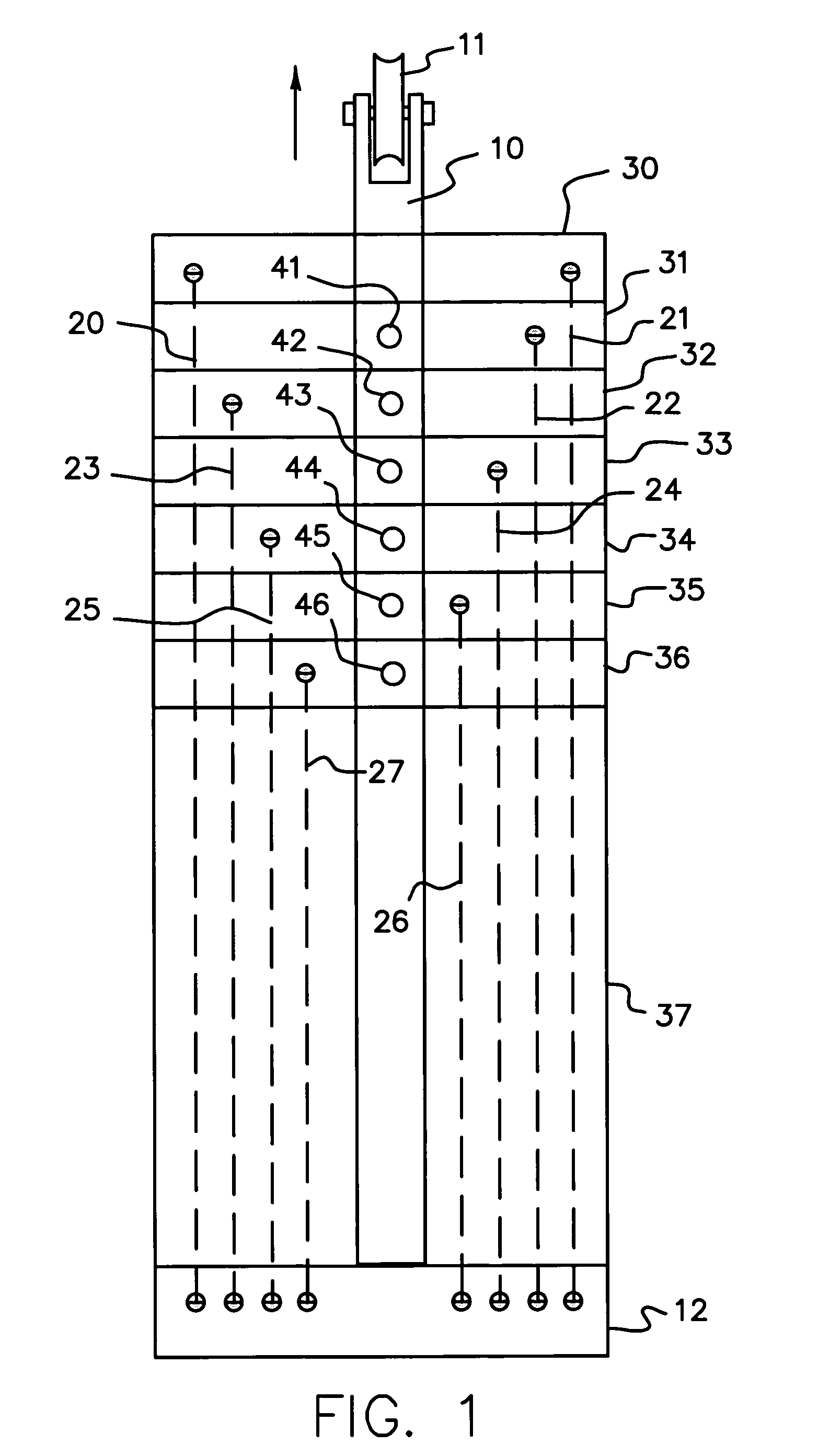
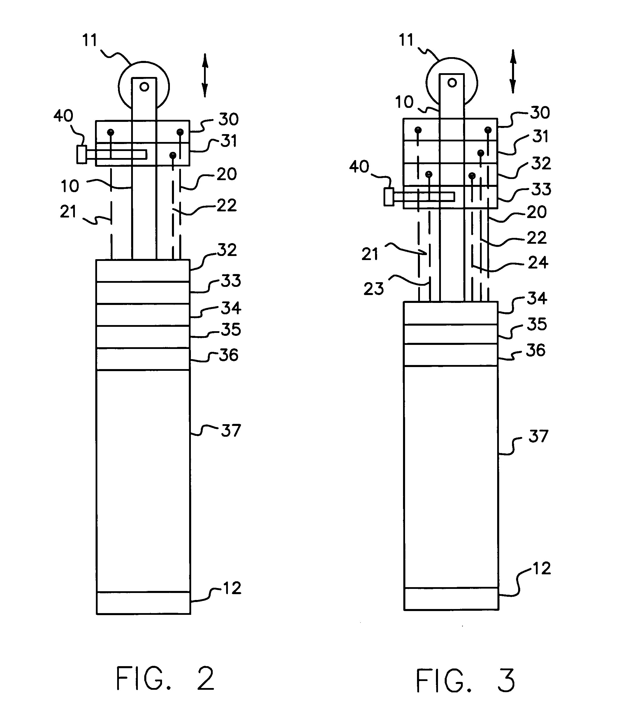
[0010]One preferred embodiment of the invention is shown in FIGS. 1–3, and another preferred embodiment, inverting the arrangement, is shown in FIG. 12. Preferably both embodiments share the features illustrated in FIGS. 4–11, and each embodiment can be modified in obvious ways, once the operating principles are fully understood.

[0011]The illustrated embodiments of the invention were devised to facilitate selection of springs deployed to resist movement for exercising purposes. The inventive spring arrangement that is workable for variable exercising resistance can also be used for other purposes such as variable counter-balancing and variable spring energy storage. These other uses may need adaptations that differ in detail from the preferred embodiments described in this application.

[0012]Considering first the embodiment of FIGS. 1–3, the movement to be variably resisted includes a movable rod 10, which moves in a spring extending or spring resisted direction away from base 12 as ...


PUM


Abstract

A variable spring resistance to movement of a rod uses a plurality of springs permanently connected between a base and a stack of end connector links extending in the direction of the rod movement. Selecting which of the links is connected to the rod then determines which of the springs are deployed to resist movement of the rod, without requiring any disconnection or reconnection of the springs. The selection can be made by a pin inserted through an aligned hole between a link and the rod. The arrangement can also be inverted with the springs connected between the links and a moving element, and the rod or other link selector being fixed to a base. Connecting one of the links to the rod then determines which of the springs will be extended between fixed and movable elements to establish a selectively variable spring resistance.

Description

RELATED APPLICATIONS[0001]This is a continuation-in-part patent application of application Ser. No. 10 / 662,214, filed 12 Sep. 2003 now U.S. Pat. No. 7,037,246, entitled “Spring Pack”, hereby incorporated by reference.BACKGROUND[0002]Exercising devices often provide variable spring resistances for humans to work against while building and training muscles. Although different numbers of springs or other elastically deformable elements can be used to provide the variable resistance, springs and bungie cords, for example, have to be hooked up and unhooked to change the amount of resistance desired. Springs not in use have to be parked out of the way, and the hooking and unhooking of tension springs is time consuming and inconvenient. The connecting and disconnecting of springs can also result in springs snapping lose from a person's grip, and can cause minor injuries such as bruised or pinched fingers.SUMMARY OF THE INVENTION[0003]This invention solves the problem of connecting and disc...

Claims


Application Information

Patent Timeline
Patent Type & Authority Patents(United States)
IPC IPC(8): A63B21/04A63B21/00A63B21/02A63B21/045A63B21/055A63B21/062A63B22/04F16F
CPCA63B21/023A63B21/156A63B21/154A63B21/04A63B21/00065A63B21/00069A63B21/0428A63B21/02A63B22/00
Inventor KIM, YONG WOO
Owner KELLION CORP
Learn More