
Battery having nonconductive core

a non-conductive core and battery technology, applied in the field of batteries, can solve the problems of shortened battery life and deterioration of the sealing performance of the battery, and achieve the effects of reducing the risk of damaging the electrode plate group upon vibration, high sealing performance and high reliability

Inactive Publication Date: 2007-03-20
GK BRIDGE 1
View PDF4 Cites 6 Cited by
  • Summary
  • Abstract
  • Description
  • Claims
  • Application Information

AI Technical Summary

Benefits of technology

The present invention aims to provide a battery that can withstand vibration and has high sealing performance, ensuring long-term reliability even in poor usage conditions. The battery includes an electrode plate group that is wound around a roll core and supported by the battery case, eliminating the risk of damage to the electrodes. This design ensures the battery's performance and reliability.

Problems solved by technology

Such a problem is critical to any batteries other than a cylindrical battery that houses a roundly wound electrode plate group in a cylindrical battery case.
Accordingly, a sealing performance of the battery is deteriorated and the battery life is shortened.

Method used


Image

  • Battery having nonconductive core
  • Battery having nonconductive core
  • Battery having nonconductive core

Examples


Embodiment Construction

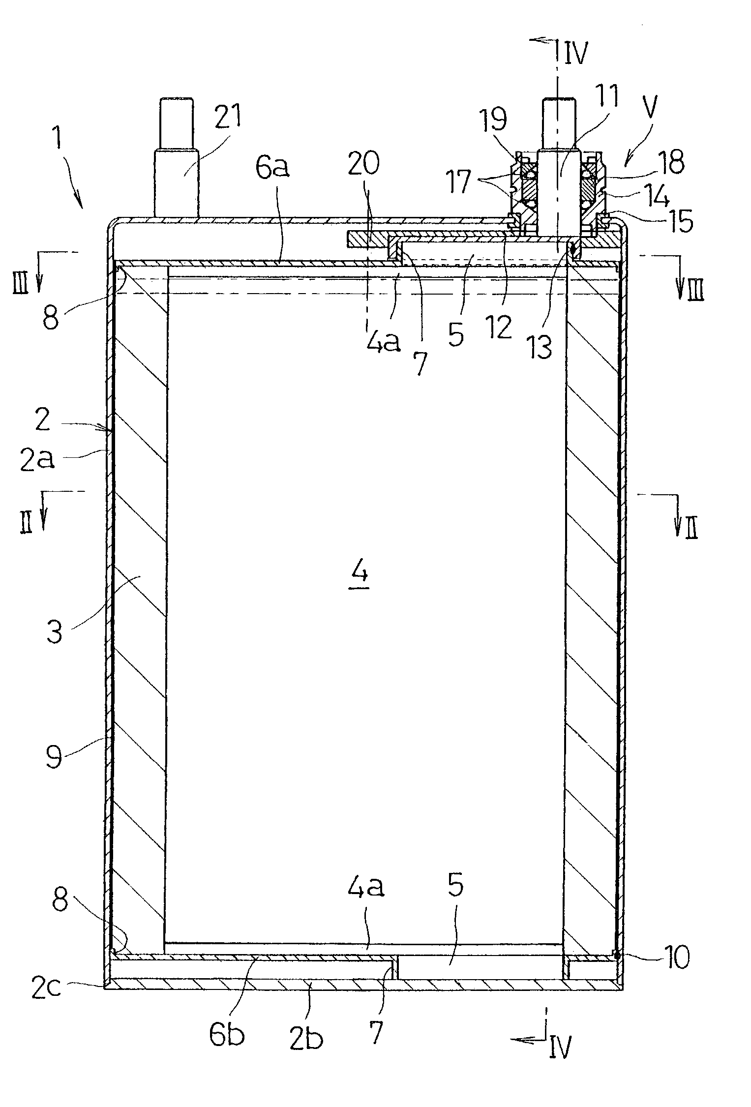
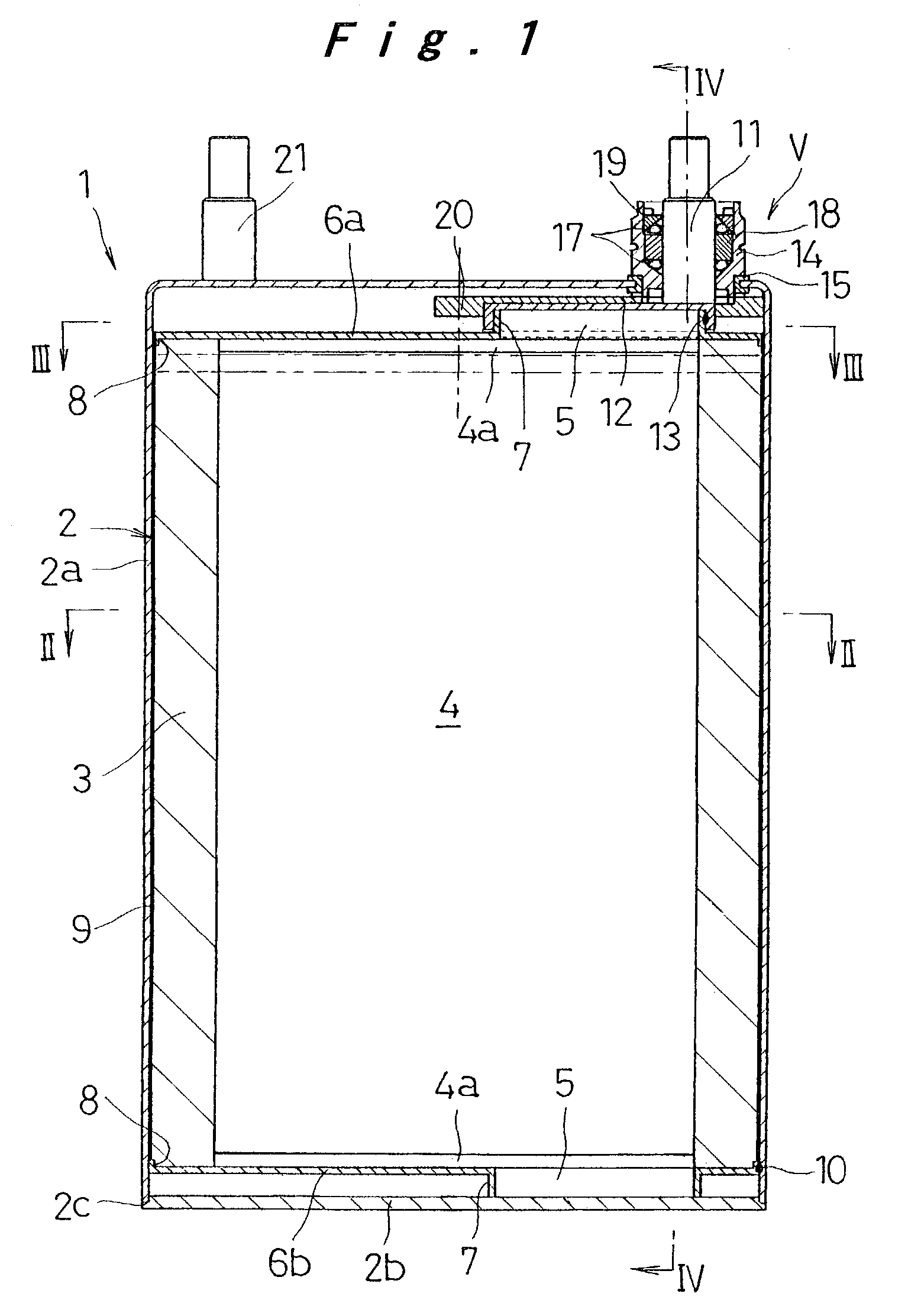
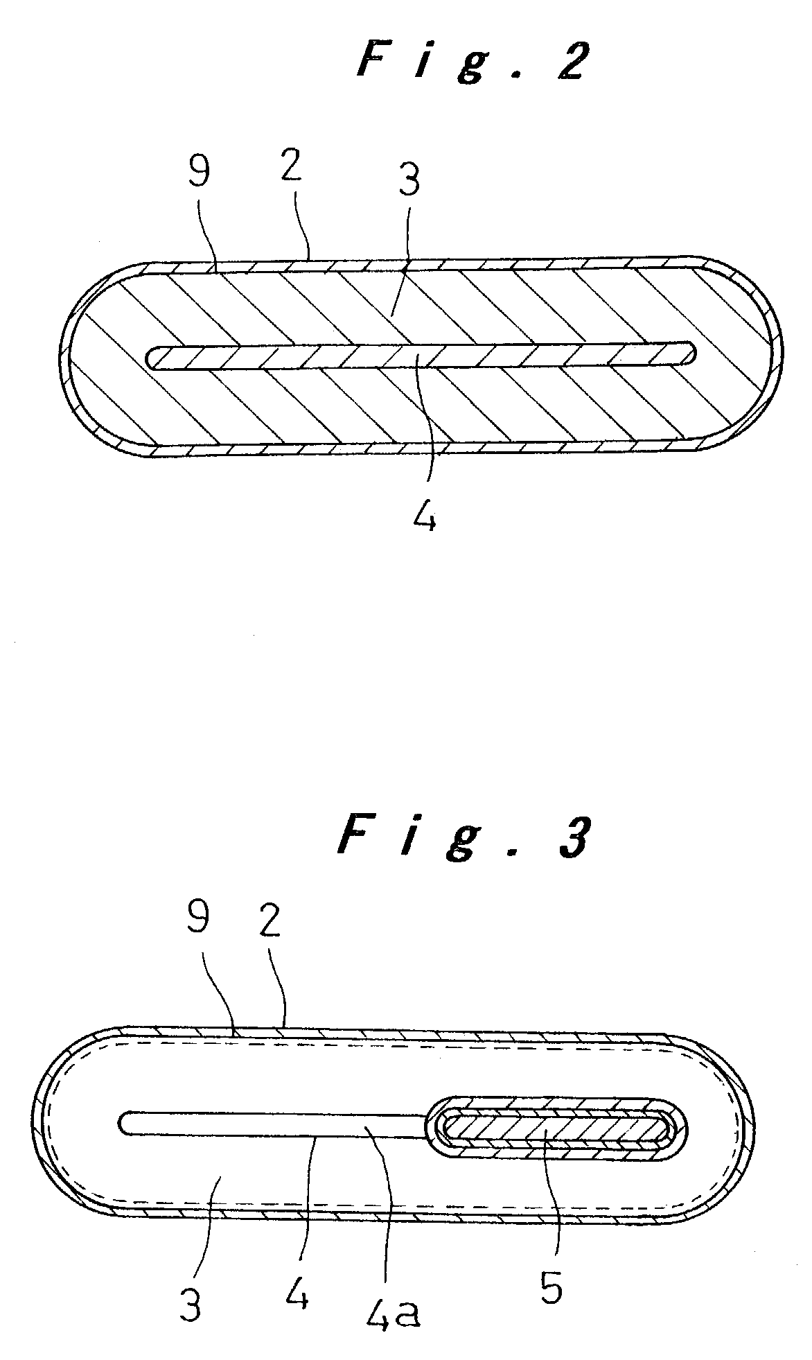
[0021]Now, a configuration of a battery according to one embodiment of the present invention will be described with reference to FIGS. 1 to 6.

[0022]In FIGS. 1 to 5, reference numeral 1 denotes a battery. The battery 1 is configured in such a manner that an electrode plate group 3, which is formed by winding a positive electrode plate and a negative electrode plate with a separator interposed therebetween, is housed in a battery case 2 together with an electrolyte solution. The battery case 2 includes a container 2a with an opening at a bottom end, and a lid plate 2b for closing the opening. The container 2a is formed into a flat block shape or an approximately prismatic shape with a transverse cross section of an oblong or a rounded rectangle. An outer periphery of the lid plate 2b is hermetically fixed to an edge of the opening of the container 2a at a welded part 2c.

[0023]The electrode plate group 3 is formed by winding the positive electrode plate and the negative electrode plat...


PUM

PropertyMeasurementUnit
shapeaaaaaaaaaa
structureaaaaaaaaaa
pressureaaaaaaaaaa

Abstract

In a battery having a structure that an electrode plate group, formed by winding a positive electrode plate and a negative electrode plate with a separator interposed therebetween, is housed in a battery case together with an electrolyte solution, the electrode plate group is rolled around a roll core, and both ends of the roll core are supported by the battery case.

Description

[0001]The present disclosure relates to subject matter contained in priority Japanese Patent Application No. 2002-94222, filed on Mar. 29, 2002, the contents of which is herein expressly incorporated by reference in its entirety.BACKGROUND OF THE INVENTION[0002]1. Field of the Invention[0003]The present invention relates to a battery, and more particularly, to a battery configured in such a manner that an electrode plate group, which is formed by winding a positive electrode plate and a negative electrode plate with a separator interposed therebetween, is housed in a battery case together with an electrolyte solution.[0004]2. Description of Related Art[0005]Electric vehicles and hybrid cars are raising expectations in recent years for solving global environmental issues, and rechargeable batteries, as their power sources, are eagerly anticipated to meet demands for higher capacity and higher output capabilities in addition to downsizing and weight-saving properties. As the rechargea...

Claims


Application Information

Patent Timeline
Patent Type & Authority Patents(United States)
IPC IPC(8): H01M6/10H01M10/04H01M50/176H01M50/186H01M50/531H01M50/55H01M50/566
CPCH01M2/06H01M2/08H01M6/10H01M2/26H01M2006/106H01M2/30H01M50/531Y02P70/50H01M50/55H01M50/186H01M50/176H01M50/566
Inventor HASHIMOTO, TATSUYAKIMURA, KENJIUEMOTO, SEIICHIYUKISADA, HIRONORINAGATANI, MASATOMOFUJII, TAKABUMI
Owner GK BRIDGE 1
Learn More