Method for calculating the conductor path of a superconductor from the coil body to the joint and associated devices

a superconductor and conductor path technology, applied in the field of superconductor conductor path calculation, can solve the problems of high-temperature superconductors, difficult to realize, and not allowing such sharp bends, and achieves good temporal stability, good resolution, and maximum magnetic field strength.

Inactive Publication Date: 2007-05-08
BRUKER BIOSPIN
View PDF6 Cites 6 Cited by
  • Summary
  • Abstract
  • Description
  • Claims
  • Application Information

AI Technical Summary

Benefits of technology

[0017]In accordance with the inventive method, the band-shaped superconductor of rectangular cross-section is bent about its broad side to a maximum bending radius rmin and can be twisted in the longitudinal direction through τ (with the dimensions of angle per unit length) but not be bent about its narrow side. The resulting path z(u) can be represented as a diagram, wherein the curve starts typically at z=u=0 and has an asymptote at a defined u-value. At this u-value, the band-shaped superconductor has reached its axial orientation and does not require further bending. The axial direction is thereby obtained with the band-shaped superconductor abutting on the cylindrical coil body, i.e. without considerably increasing the space requirements beyond the radius of the cylindrical coil body. There is no interference with possible coil sections located further outwardly or other geometrical obstacles. Taking into consideration the minimum bending radius eliminates the risk of damage to the superconductor. The predetermined torsion defines the most compact possible shape for the band-shaped superconductor. This is particularly important when several axial conductor sections are provided at the end of a coil winding, i.e. for current supply and discharge. Towards this end, the conductor sections must not cross, i.e. the transition from azimuthal behavior to axial behavior must be obtained through a short space, preferably within half a perimeter.
[0038]The invention also concerns an NMR (nuclear magnetic resonance) high-field magnet coil system comprising superconducting conductor structures for generating an extremely homogeneous and highly temporally stable magnetic field B0 in a measuring volume, characterized in that the magnet coil system comprises an inventive high-field magnet coil. Particularly important to NMR is the avoidance of drifts for high magnetic field strengths obtained with compact coil arrangement, wherein elimination of joints in the region of considerable magnetic field strengths is particularly advantageous.

Problems solved by technology

A major problem in magnet construction is the transition points points) from one superconducting conductor section to another.
This may be difficult to realize when it is geometrically not possible (or undesirable for other reasons) to guide the band-shaped superconductor tangentially away from the coil winding (i.e. tangential to the surface of the cylindrical coil body and approximately perpendicular to the cylinder axis) due for example to the presence of radially outer coil sections which axially project beyond the coil winding in solenoidal coils.
High-temperature superconductors (and other inflexible superconducting materials) do not permit such sharp bends.
These joints at the edge of the coil winding limit the efficiency of the overall magnet coil for many applications.

Method used


Image

  • Method for calculating the conductor path of a superconductor from the coil body to the joint and associated devices
  • Method for calculating the conductor path of a superconductor from the coil body to the joint and associated devices
  • Method for calculating the conductor path of a superconductor from the coil body to the joint and associated devices

Examples


Embodiment Construction

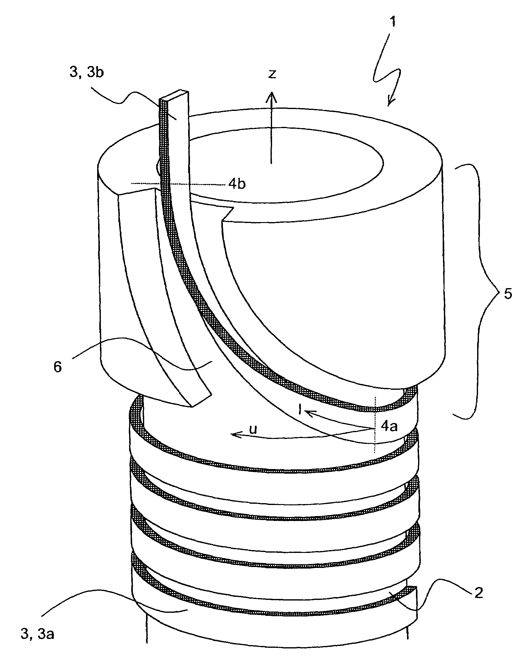
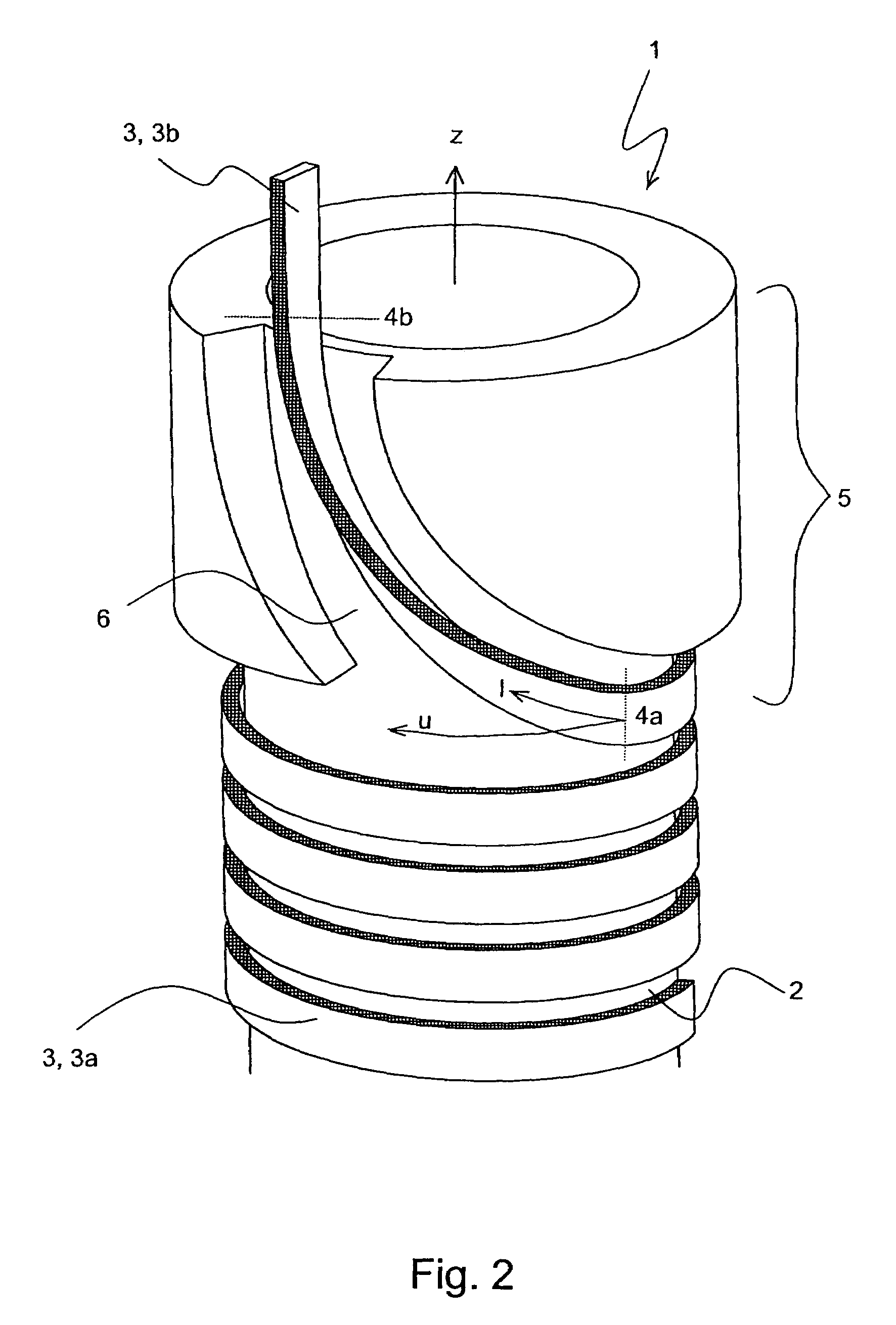
[0045]The inventive method for calculating a path of a conductor guidance is illustrated with a flat high-temperature superconducting band of rectangular cross-section having the following bending parameters:[0046]Minimum bending radius about the broad side: rmin [0047]Very large (i.e. infinite) minimum bending radius across the narrow side[0048]Maximum admissible torsion: τmax

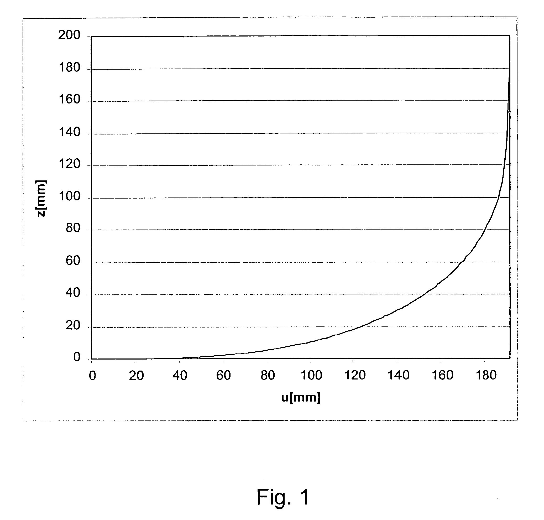
The band is wound onto a coil body to a radius r0>rmin and is to be transferred onto the cylinder envelope (radius r0) from the azimuthal to the axial direction without exceeding the bending parameters. If z is the axial coordinate and u the azimuthal coordinate, the band describes a curve z(u) on the cylinder envelope surface. To turn the band out of the azimuthal direction, it must at first be raised since bending about the narrow side is not possible or only possible to a very limited degree. The further the band is raised, the more it can be bent in the u-z plane. If it is perpendicular on the u-z plane, ...


PUM

PropertyMeasurementUnit
operating temperatureaaaaaaaaaa
angleaaaaaaaaaa
radius r0aaaaaaaaaa

Abstract

A method for calculating the shape of a band-shaped superconductor (3) of a solenoid-shaped coil section of a high-field magnet coil (1) in a transfer region (5) is characterized in that the band-shaped superconductor (3) is changed in the transfer region from a first orientation (3a) tangentially flatly abutting on the surface of a cylindrical coil body (2) and substantially perpendicular to the longitudinal direction of the cylindrical coil body (2) to a second orientation (3b) with its narrow side seating on the surface of the cylindrical coil body and parallel to the longitudinal direction (or vice versa). The path z(u) is determined from the integral-differential equationz″⁡(u)(1+z′⁡(u)2)32=sin⁢⁢(τ⁢⁢∫0u⁢ⅆu^⁢1+z′⁡(u^)2)rminwherein z: axial coordinate; u: azimuthal coordinate; û: auxiliary coordinate; τ: constant torsion in the transfer region; rmin minimum bending radius of the band-shaped superconductor, and wherein the position z=0, u=0 is associated with a boundary point 4a, 4b of the transfer region. This permits conductor guidance of a brittle band-shaped superconductor of a solenoidal coil section in an axial direction in a compact construction without joints.

Description

[0001]This application claims Paris Convention priority of DE 102 60 728.1 filed Dec. 23, 2002 the complete disclosure of which is hereby incorporated by reference.BACKGROUND OF THE INVENTION[0002]The invention concerns a method for calculating the travel of a band-shaped superconductor in a coil section of a high field magnet coil through a transition region towards or away from the coil section, wherein the coil section is wound onto a cylindrical coil body in the shape of a solenoid.[0003]A high field magnet coil with conventional conductor guidance is disclosed e.g. in “Supraleitende Magnete für die NMR-Spektroskopie” (superconducting magnet for NMR spectroscopy) by Rainer Haeβner, TU Munich, 21.12.2001, URL:http: / / www.org.chemie.tu-muenchen.de / people / rh / nmrueb / magnet2.pdf (see FIGS. 2 and 5).[0004]Superconducting magnet coils are used for producing maximum magnetic field strengths, in particular for NMR (nuclear magnetic resonance) applications. Superconductors can carry electr...

Claims


Application Information

Patent Timeline
Patent Type & Authority Patents(United States)
IPC IPC(8): H01F7/00H01F1/00G01R33/3815G06F17/50H01F6/06
CPCG01R33/3815G06F17/5036H01F6/06G06F30/367
Inventor NIEMANN, VOLKERSCHLENGA, KLAUS
Owner BRUKER BIOSPIN
Why Eureka
Try Eureka