Device for crimping element to be crimped on part

A technology of crimping components and connectors, applied in metal processing equipment, metal processing, manufacturing tools, etc., can solve problems such as immediate shutdown, broken free end of punch, damaged positioning parts, etc., to achieve the effect of eliminating the risk of damage

Active Publication Date: 2011-10-26
RENAULT SA
View PDF5 Cites 7 Cited by
  • Summary
  • Abstract
  • Description
  • Claims
  • Application Information

AI Technical Summary

Problems solved by technology

The element to be crimped at the bottom has a tendency to flatten and spread out, damaging the retainer - breaking it - and/or the free end of the punch
Th

Method used


Image

  • Device for crimping element to be crimped on part
  • Device for crimping element to be crimped on part
  • Device for crimping element to be crimped on part

Examples


Embodiment Construction

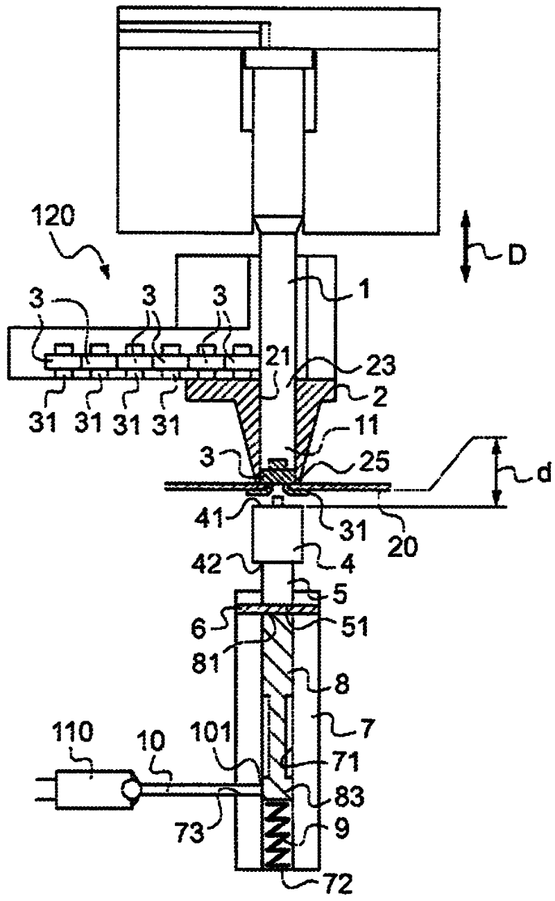
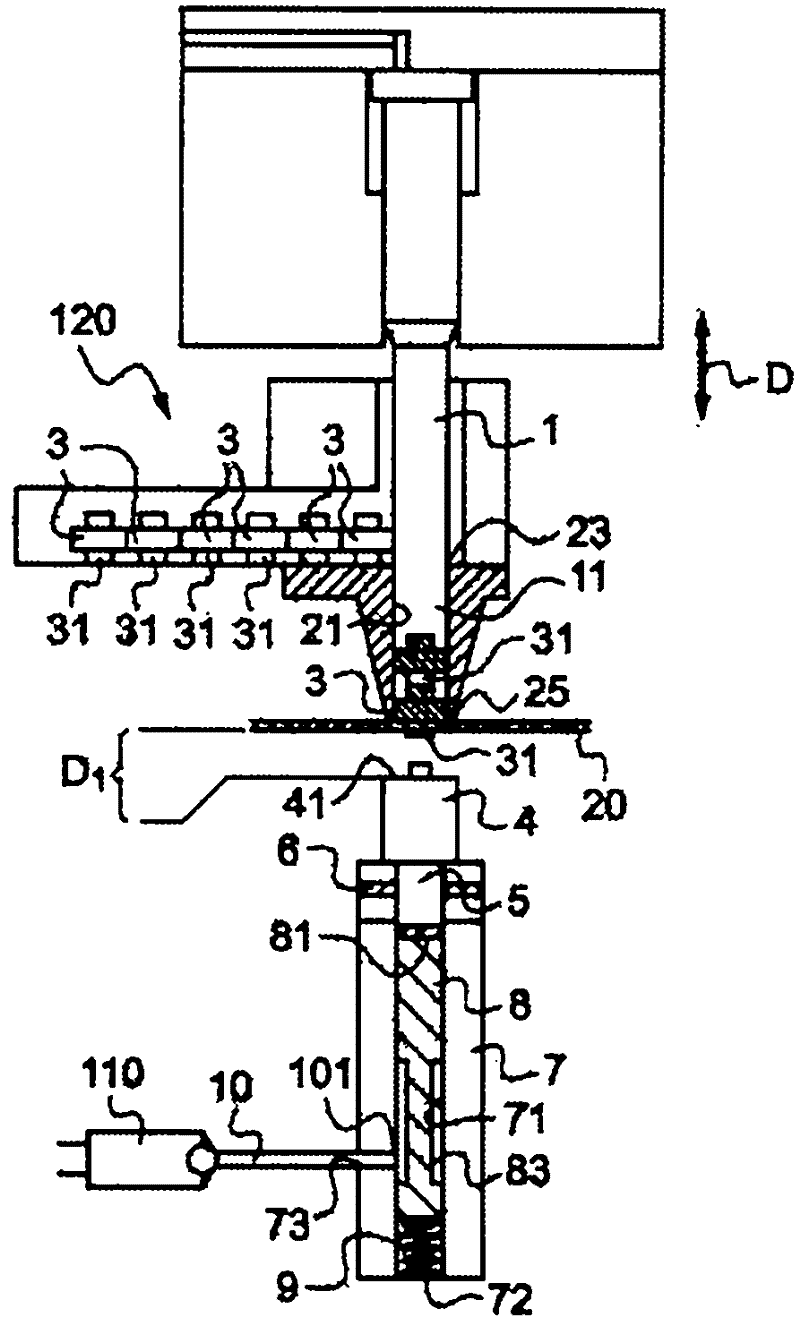
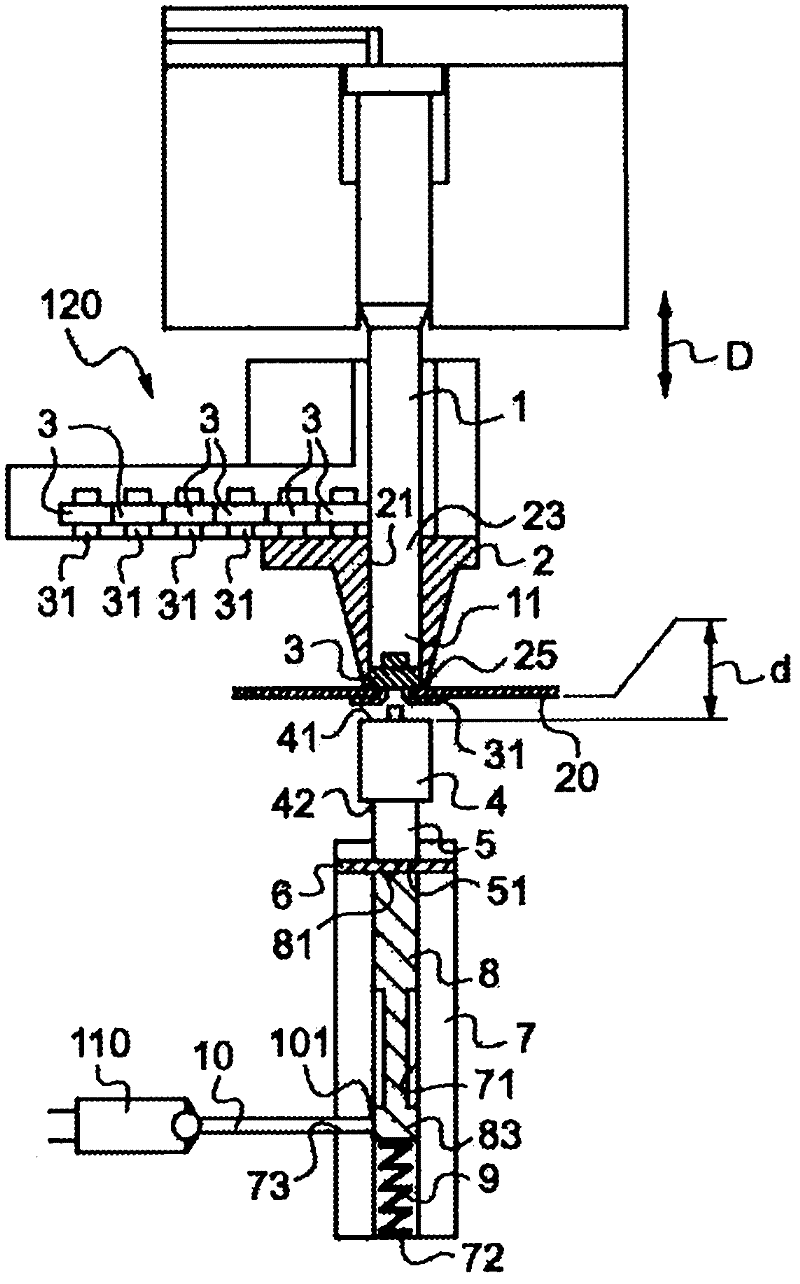
[0023] figure 1 One embodiment of the device of the invention is shown. In the embodiments described here, crimping is performed by deforming a part of the element to be crimped. Obviously, the device of the invention also covers the crimping of an element to be crimped to a part by deforming a part of the part, possibly in combination with the deformation of the element to be crimped.

[0024] The device 1 comprises a punch 1 with a free end 11 . The punch 1 is capable of a translational movement in a direction D, which in this particular example is a vertical direction. The device comprises a positioning element 2 in which a vertical channel 21 is formed, ie a channel parallel to the direction D. Channel 21 has an inlet 23 and an outlet 25 . The positioner 2 is arranged such that the free end 11 of the punch 1 can move in the channel 21 . The punch 1 moves between a raised position, in which the free end 11 of the punch 1 is located above and at a distance from the entr...


PUM


Abstract

The invention relates to a device for crimping an element (3) to be crimped on a part (20) with a crimping surface, said device including: a punch (1), translatably mobile in a direction D and suitable for applying, in said direction D, to said element (3) to be crimped, a force with a given intensity in order to crimp said element (3) to be crimped; a part (2) for positioning said element (3) tobe crimped; and a percussion die (4) with one operational surface (41), kept at a predetermined distance (d) relative to said outlet (25) of the passage (21) arranged in said positioning part (2). According to the invention, said device comprises a frangible element (6), which holds said die (4) and which is capable of breaking when a force with an intensity greater than a maximum value is exerted on said operational surface (41).

Description

technical field [0001] The invention relates to a device for crimping an element to be crimped on a component, in particular a motor vehicle component. Background technique [0002] Crimping is a simple operation used to assemble two parts. Some material deformation of the part to which the crimping element is crimped or the crimping element itself, or both. Crimps are used to hold components in place without using solder. For example, to secure a nut to a part without deforming the part, a nut can be produced with a central ring or guide that will pass through the other side of the part and fold over - like a rivet, this It's called a crimp nut. Like riveting, this form of assembly cannot be disassembled. It is also possible to fix the element to be crimped by deforming the part to which it is fixed. In this case, the part may not have holes. [0003] The crimping device, also commonly referred to as a crimper, comprises a punch capable of translational movement and a...

Claims


Application Information

Patent Timeline
IPC IPC(8): B23P19/06
CPCB23P19/062
Inventor F·萨尔瓦蒂E·斯蒂内H·法松
Owner RENAULT SA
Why Eureka
Try Eureka