
Hydraulic control for a longwall support

a technology of hydraulic control and longwall support, which is applied in the direction of mine roof support, coupling, mining structure, etc., can solve the problems of leakage and the risk of serious injuries, and achieve the effect of eliminating the risk of hydraulic leakage or bursting lines

Active Publication Date: 2006-03-02
TIEFENBACH CONTROL SYST
View PDF3 Cites 7 Cited by
  • Summary
  • Abstract
  • Description
  • Claims
  • Application Information

AI Technical Summary

Benefits of technology

[0004] The advanced characteristic feature of this hydraulic control consists in arranging the control valves for actuating the biasing elements of a face support framework not only in the region of the face support framework, but also on the same and even on the respective biasing element. No piping is needed between the control valve and the associated biasing element. The biasing element and associated control valves may be constructed as one structural unit, and in particular be tested before installation. Errors can be prevented when assembling control valves and biasing elements and when laying hoses between control valves and biasing elements. The risk of damage to piping is eliminated, which also reduces the danger of accidents significantly. In this connection, one needs to take into account that because of high pressures of more than 300 bars (4,351 psi), any leakage is also connected with the risk of serious injuries. Yet, the piping remains, which is needed in each face support framework for a connection between the control valves and the pressure line that extends over the length of the longwall (high-pressure line). Insofar it is a further object to reduce or eliminate the risk of leakages and injuries that are caused thereby.
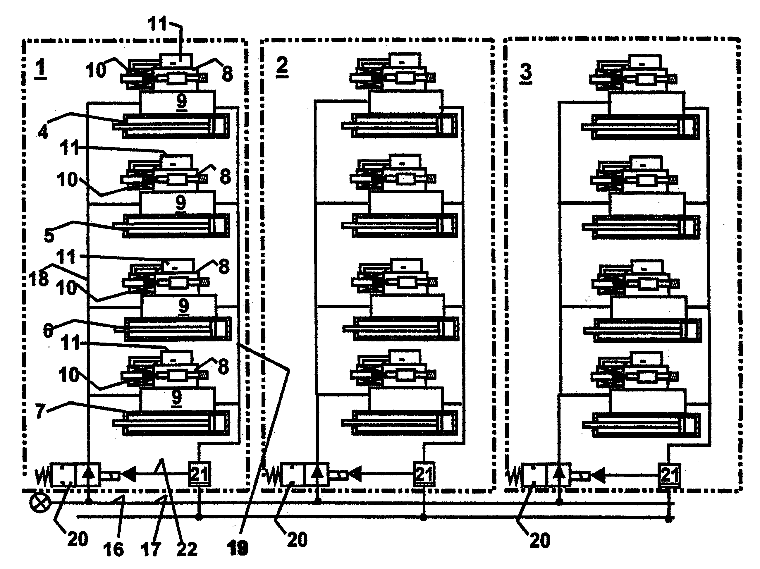
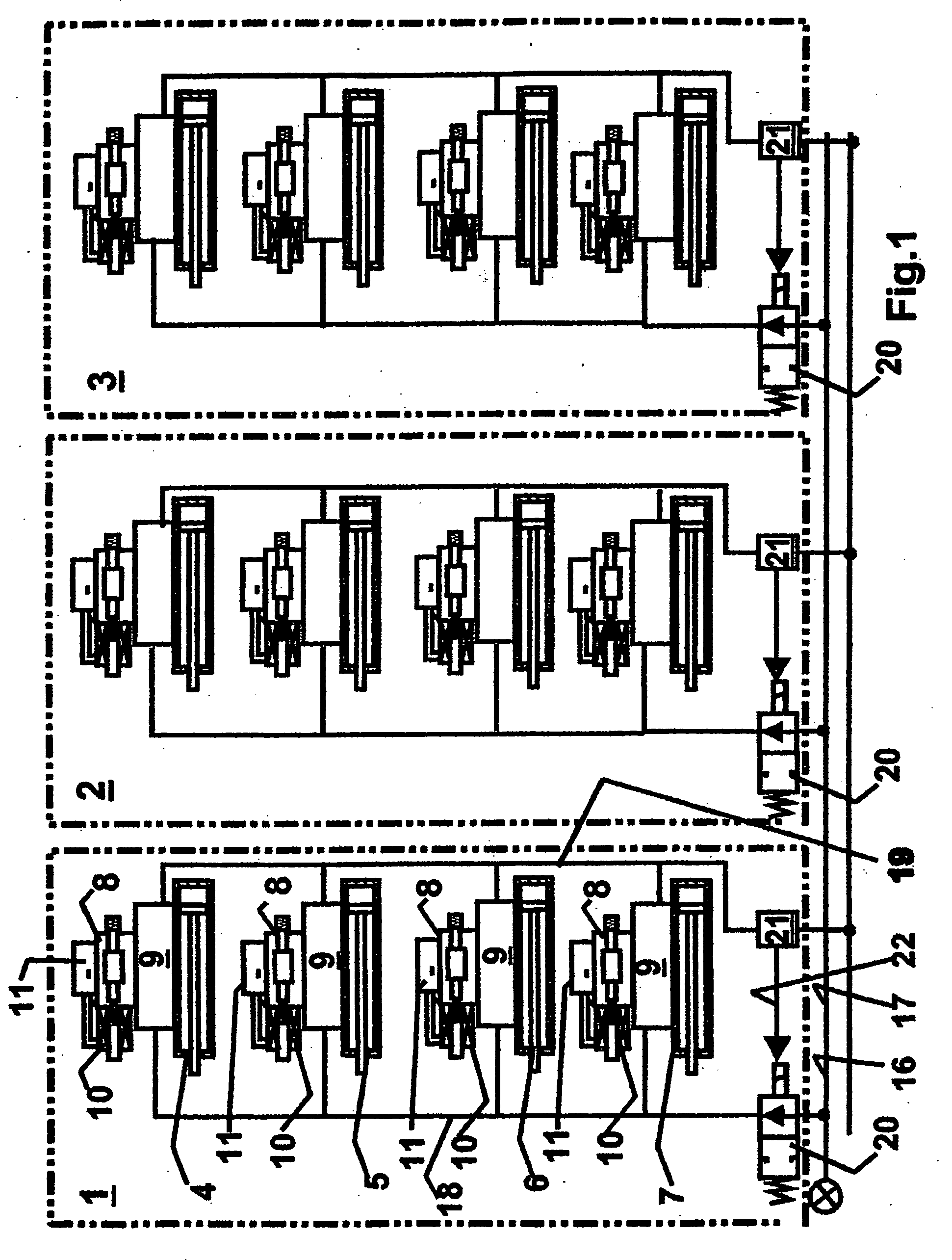
[0008] In accordance with the invention, a plurality of control valves of a face support framework are combined to groups and respectively connected via a common group supply line and group return line to the longwall pressure line or the longwall return line. However, it is also possible to combine in this manner all control valves of a face support framework to a group. In this case, only one stop valve is associated with each face support framework with the advantage that in the static state of this face support framework, i.e., when no support functions are performed, the entire face support framework is switched to a pressureless state, so that a risk of bursting lines or hydraulic leakages is eliminated.

Problems solved by technology

In this connection, one needs to take into account that because of high pressures of more than 300 bars (4,351 psi), any leakage is also connected with the risk of serious injuries.

Method used


Image

  • Hydraulic control for a longwall support
  • Hydraulic control for a longwall support
  • Hydraulic control for a longwall support

Examples


Embodiment Construction

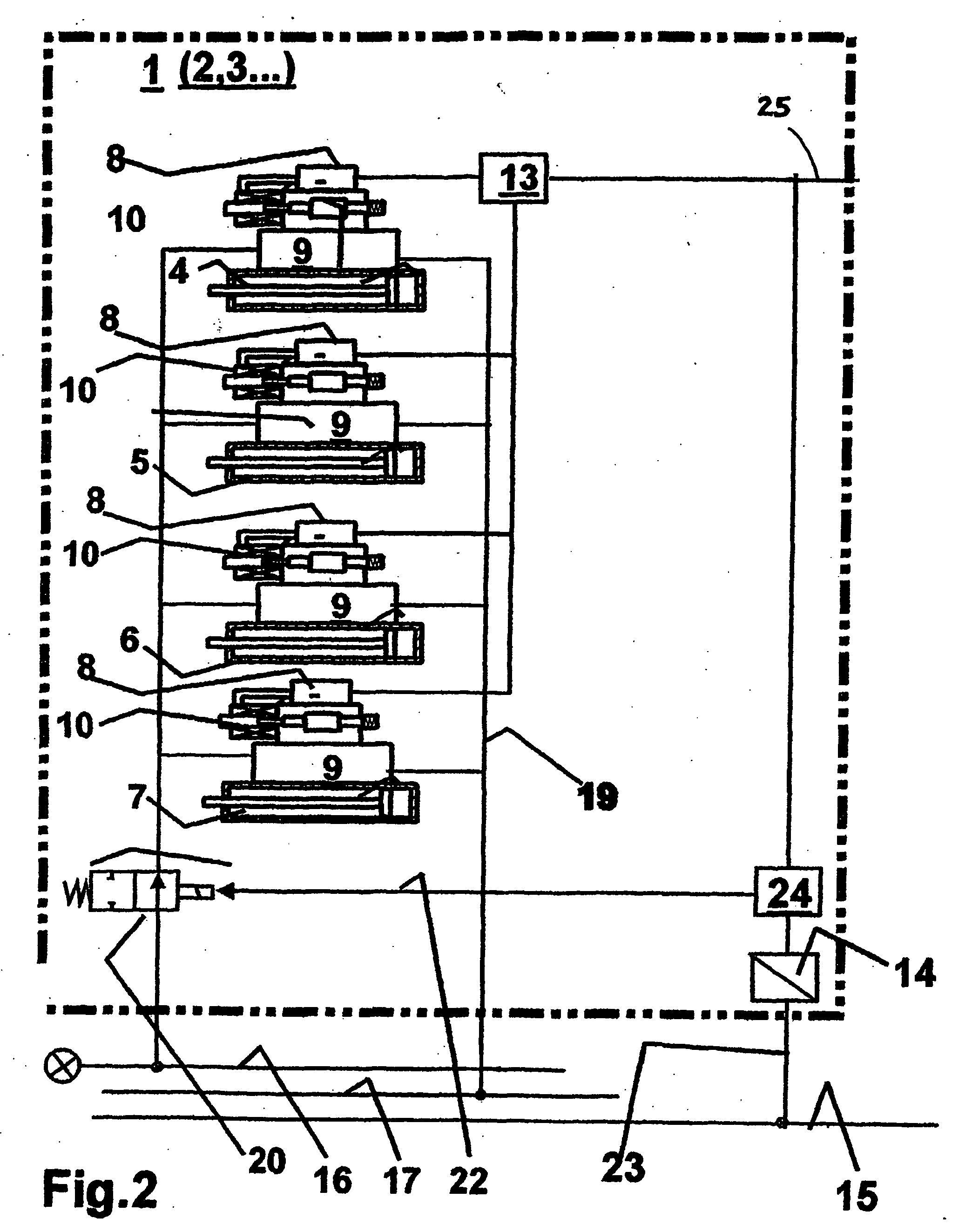
[0011]FIG. 1 schematically illustrates three face support frameworks 1-3. Each face support framework includes biasing elements 4, 5, 6, 7 in the form of cylinder-piston units. Each biasing element is actuated by a pilot valve 8 and a thereby activated main control valve 9. To actuate the pilot valve 8, one uses a magnet 10 on the one hand and a microprocessor 11 on the other hand. The latter is controlled by a longwall support controller 13, which is shown in FIG. 2. A longwall support controller is associated with each face support framework. The longwall support controllers of a plurality of face support frameworks are interconnected by a common bus line 25. The commands for activating the above-described functions of the individual longwall supports can be triggered as a function of the advance of the mining machine, automatically, by hand in a central control room, by hand on one of the adjacent longwall support controllers, or on a portable hand set.

[0012] Associated with eac...


PUM


Abstract

A hydraulic control for a longwall support with a plurality of face support frameworks (1-3), which are adapted to be actuated in the sense of longwall support functions, in particular in the sense of the longwall support operations: robbing, advancing, and setting, comprises hydraulic control valves (8, 9) for each of the biasing elements, which are each arranged in close spatial relationship with the biasing elements, and subdivided into groups. Each group connects to a hydraulic pressure line (16), which extends over the longwall length of a plurality of face support frameworks, via a group connection line (18), which can be blocked by a group stop valve (20) as a function of the actuation of the control valves, specifically, when all control valves are not actuated and all biasing elements of the group are in a static state.

Description

CROSS REFERENCE TO RELATED APPLICATION [0001] The present application is a continuation of international application PCT / DE2004 / 000787, filed 15 Apr. 2004, and which designates the U.S. The disclosure of the referenced application is incorporated herein by reference.BACKGROUND OF THE INVENTION [0002] The invention relates to a hydraulic control for a longwall support. A hydraulic control of this type is disclosed in WO 02 / 068798 A1. [0003] The invention relates to the hydraulic control for a plurality of face support frameworks. The face support frameworks are arranged along a coal seam. The coal seam is worked with the cutting device of a mining machine, for example, the cylindrical cutters of a coal cutting machine. The coal that has been dislodged by the cylindrical cutters of the coal cutting machine is loaded on a conveyor. The conveyor comprises a trough, which is subdivided into individual units (trough chutes). Each trough chute connects to a longwall support unit by a biasi...

Claims


Application Information

Patent Timeline
IPC IPC(8): F16D31/02E21D23/26
CPCE21D23/26
Inventor KUSSEL, WILLI
Owner TIEFENBACH CONTROL SYST
Learn More