Offset PWM signals for multiphase motor

a multi-phase motor and offset technology, applied in the direction of electric motor control, dynamo-electric converter control, control system, etc., can solve the problems of increasing the overall size of the drive circuitry of the motor, increasing the cost of the sensors and the related conditioning circuitry associated with each sensor, and increasing the cost of the motor driv

Active Publication Date: 2007-03-20
COPELAND LP
View PDF32 Cites 107 Cited by
  • Summary
  • Abstract
  • Description
  • Claims
  • Application Information

AI Technical Summary

Problems solved by technology

The cost of the sensors and the related conditioning circuitry associated with each sensor adds cost to the motor drive.
The sensors also take up additional space thereby making the overall size of the drive circuitry of the motor larger.
If individual phase current information is needed, more complex control methods and systems are employed.

Method used


Image

  • Offset PWM signals for multiphase motor
  • Offset PWM signals for multiphase motor
  • Offset PWM signals for multiphase motor

Examples


Embodiment Construction

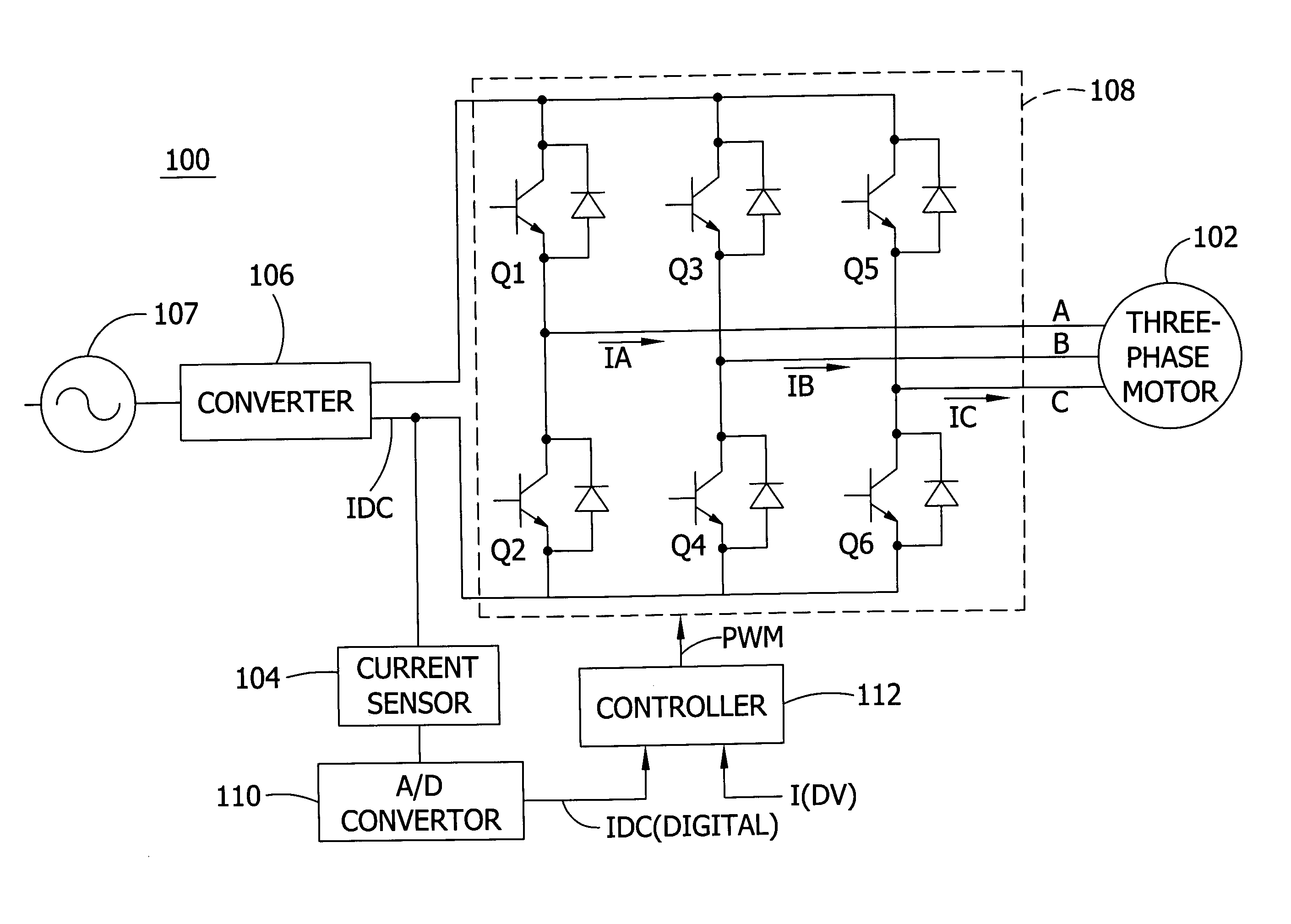
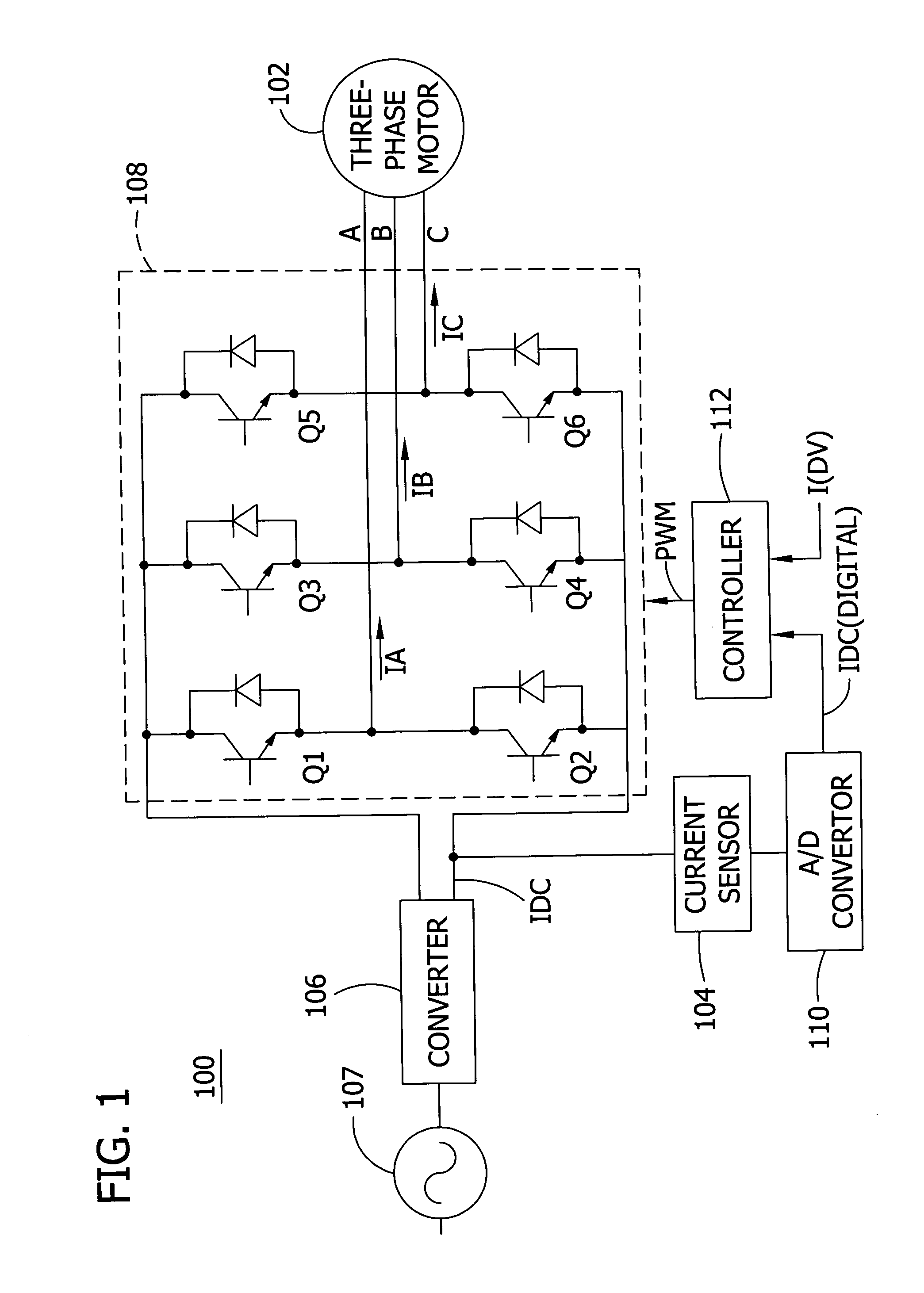
[0012]The present invention is illustrated in one embodiment in FIG. 1, which is a diagram partially in block form and partially in schematic form showing an apparatus 100 for supplying current to each phase of multiphase alternating current motor such as a three phase motor 102 using a single current sensor 104. The apparatus 100 includes a converter 106 for converting alternating current from a three-phase AC (Alternating Current) power source 107 into direct current used to power a three phase motor 102. An inverter 108 comprises a switching array including a pair of switching devices Q1 and Q2, a pair of switching devices Q3 and Q4, and a pair of switching devices Q5 and Q6 for supplying power to the respective phases. Generally, either the upper or lower switch for a given phase is always on, except for brief periods during switching. The inverter 108 converts direct current from the converter 106 into alternating current and provides the alternating current to the three-phase ...


PUM


Abstract

A multi phase motor includes a switching array for interconnecting a power source to each phase. A current sensor senses current supplied from the power source via the switching array to the winding and a controller generates offset PWM signals for controlling the switching array to supply power to each of the phases of the winding. The offset timing allows the individual phase currents to be determined from a single current sensor.

Description

FIELD OF THE INVENTION[0001]The present invention generally relates to current sensing in multiphase motors and, in particular, using a single current sensor for sensing current in each phase of a multiphase motor drive.BACKGROUND OF THE INVENTION[0002]Three current sensors are normally needed to measure the currents in each phase of a three phase motor. Many control methods and systems for commutating the switches which selectively supply power to each of the three phases of a motor require three signals, one from each of the three current sensors in each phase, for operation. Some control methods and systems employ the signal from a current sensor connected to a bus supplying current to the three phases. The cost of the sensors and the related conditioning circuitry associated with each sensor adds cost to the motor drive. The sensors also take up additional space thereby making the overall size of the drive circuitry of the motor larger.[0003]Single current sensors are used in si...

Claims


Application Information

Patent Timeline
Patent Type & Authority Patents(United States)
IPC IPC(8): H02P11/00
CPCH02M7/53873H02P2205/01H02M2001/0009H02M1/0009H02P7/29
Inventor SKINNER, JAMES L.GREEN, CHARLES E. B.
Owner COPELAND LP
Why Eureka
Try Eureka