
USB 1.1 for USB OTG implementation

a technology of usb 1.1 and otg, which is applied in the direction of logic circuit coupling/interface arrangement, pulse technique, instruments, etc., can solve the problem of not enabling a standard usb 1.1 devi

Active Publication Date: 2007-03-20
TEXAS INSTR INC
View PDF5 Cites 39 Cited by
  • Summary
  • Abstract
  • Description
  • Claims
  • Application Information

AI Technical Summary

Benefits of technology

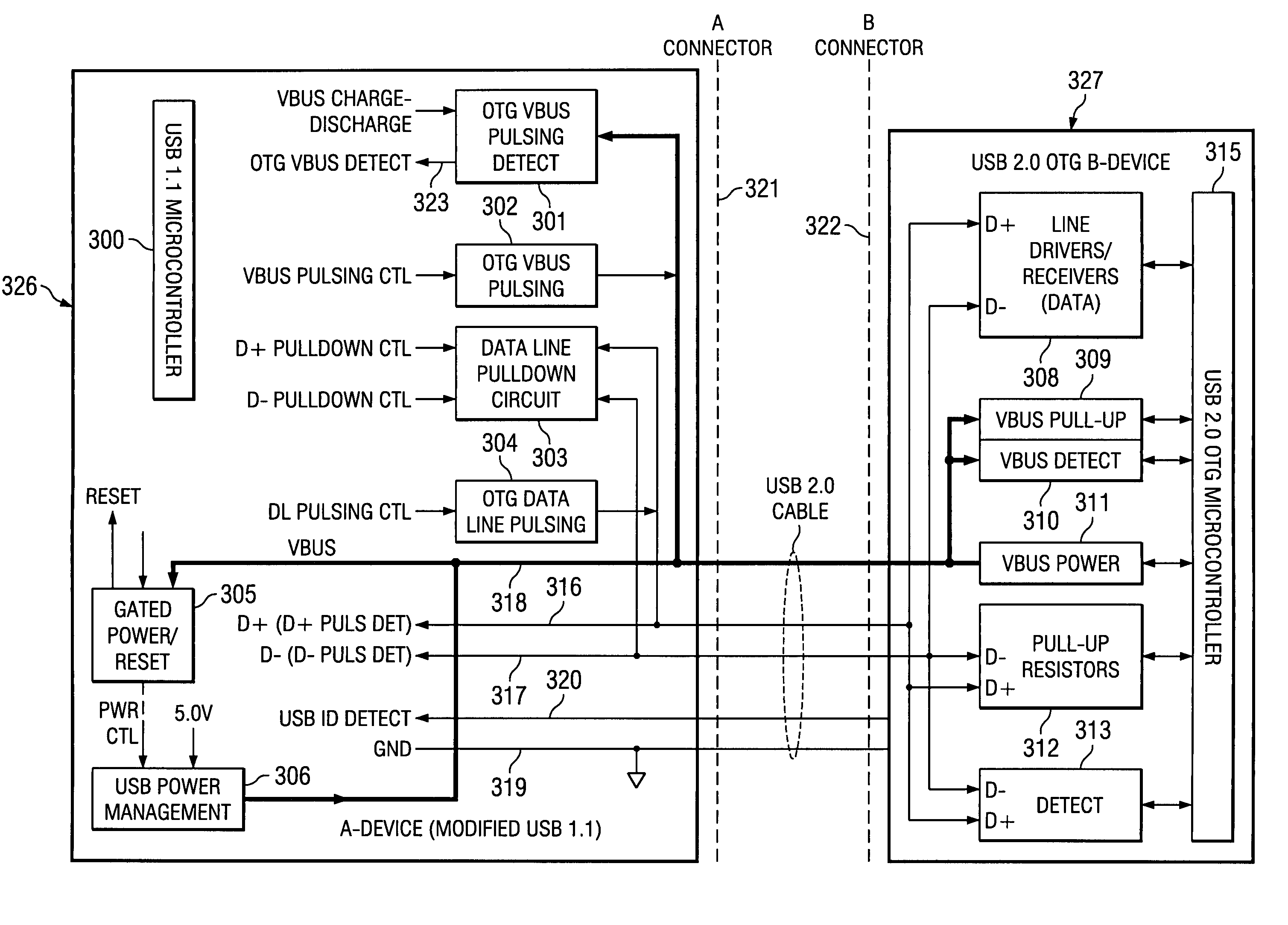
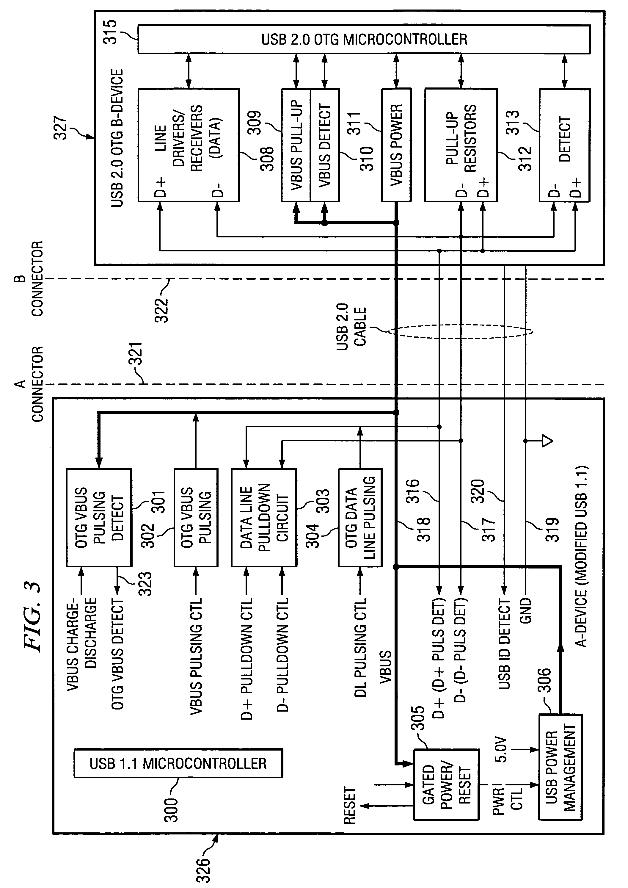
The present invention describes a way to make it possible for a standard USB 1.1 device to communicate with a USB 2.0 OTG device. This is made possible through a low-cost interface function that mimics the functions of a USB 2.0 OTG device. The interface circuitry and programming upgrades ensure that the USB 1.1 system complies with the specifications of the USB 2.0 OTG device. The technical effect of this invention is the seamless communication between different USB devices, making it more convenient and efficient for users.

Problems solved by technology

Prior techniques allow the OTG device to communicate only with another OTG device and do not enable a standard USB 1.1 device to communicate with a USB OTG device.

Method used


Image

  • USB 1.1 for USB OTG implementation
  • USB 1.1 for USB OTG implementation
  • USB 1.1 for USB OTG implementation

Examples


Embodiment Construction

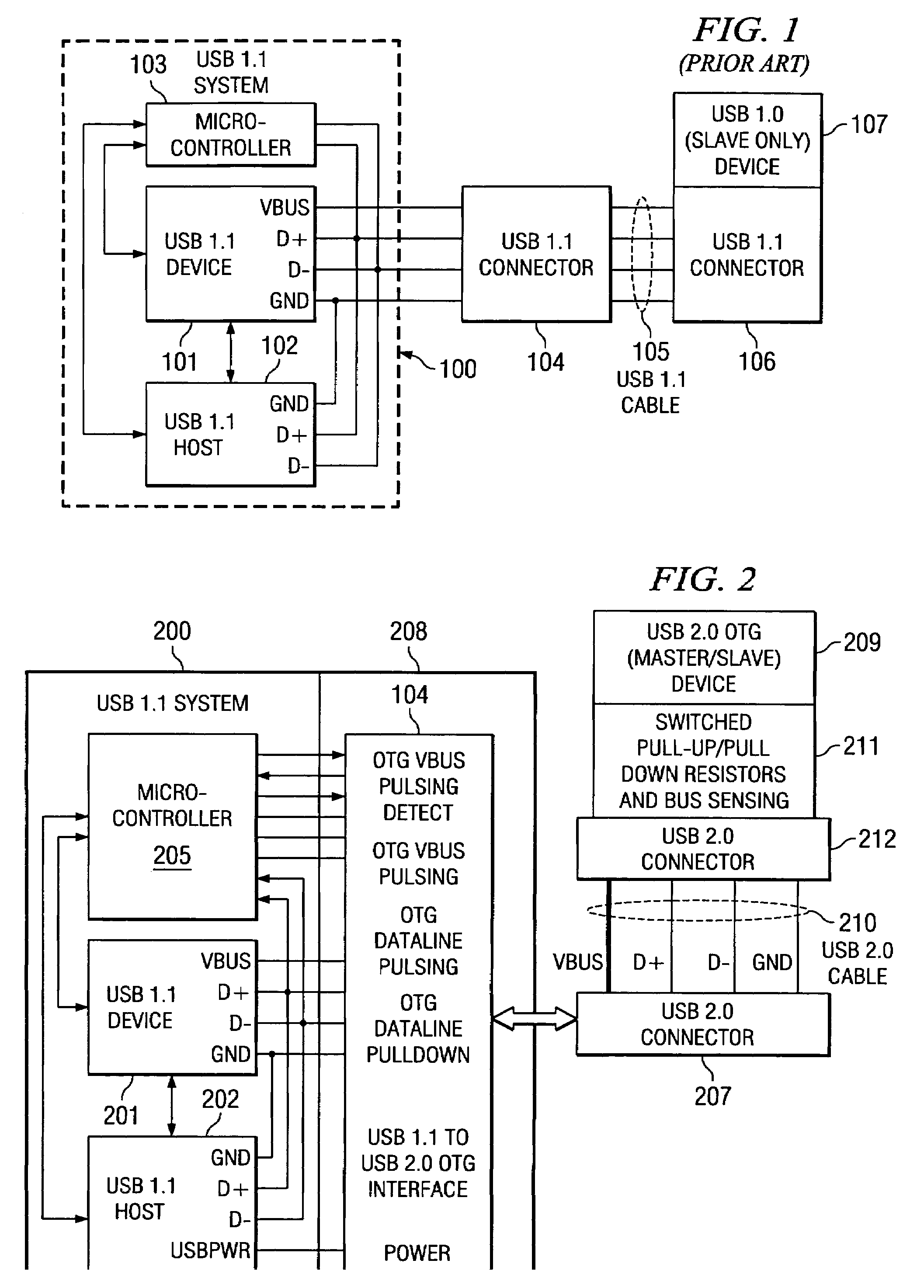
[0058]FIG. 2, illustrates a block diagram of this invention. This includes a hardware interface function 208, which enables the modified USB 1.1 system 200 including a microcontroller 205, an USB 1.1 device 201 and an USB 1.1 host 202 and the mixed signal interface circuit 208 to communicate seamlessly with an USB 2.0 OTG device 209. The full interface uses both software programming of the microcontroller device 205 and the hardware interface 208. The USB 2.0 OTG device 209, which may be either single role (slave) or dual-role (host / slave), is connected to the USB 1.1 system 200 through USB connectors 207 and 212 and USB cable 210. Microcontroller 205 performs internal frame timing functions to synchronize the occurrence of pulsing, detect and pull-up / pull-down control signals to implement SRP and HNP. USB 1.1 device 201 and host 202 hardware need no modification to achieve the interface, although microcontroller programming is required and additional microcontroller input / output si...


PUM


Abstract

This invention enables a USB 1.1 device and a USB 1.1 host to communicate seamlessly with a USB OTG device. The invention complies with both USB 1.1 and OTG specifications. The invention includes the USB 1.1 host, USB 1.1 device and mixed signal circuits to implement USB OTG functions. The mixed signal components are controlled by the USB 1.1 device microcontroller. The invention is a cost effective implementation compared to a custom ASIC design for USB OTG implementation.

Description

TECHNICAL FIELD OF THE INVENTION[0001]The technical field of this invention is retrofit circuits enabling a USB 1.1 device to operate as a USB OTG device.BACKGROUND OF THE INVENTION[0002]Universal Serial Bus (USB) ports have been employed widely to connect peripheral devices to computers. Typical peripheral connections connected through USB are Printers, scanners, zip drives, digital cameras, mice, joysticks, modems, speakers, telephones, video phones and network connections.[0003]Almost all peripheral devices now come in a USB version. The Universal Serial Bus allows for the connection of up to 128 devices to a computer. Upon connection of a new device the operating system auto-detects it and requests driver input. If the device has already been installed, the computer activates it and starts communication with it.[0004]FIG. 1 illustrates a conventional USB 1.1 master-slave system 100 connected to a USB 1.1 slave only device 107. The USB master-slave system 100 includes a USB 1.1 d...

Claims


Application Information

Patent Timeline
Patent Type & Authority Patents(United States)
IPC IPC(8): H03K19/0175G06F13/42H03K19/00H03K25/00
CPCG06F13/4081
Inventor ZHU, XIAOMING
Owner TEXAS INSTR INC
Learn More