Labeler for pipes, conduits, tubes, and rods
a technology for labeling pipes and conduits, applied in the direction of identification means, instruments, gymnastics, etc., can solve the problems of increasing the complexity of communication, data, plumbing, gaseous and electrical systems in use, and difficulty in writing on a round or curved surface,
- Summary
- Abstract
- Description
- Claims
- Application Information
AI Technical Summary
Benefits of technology
Problems solved by technology
Method used
Image
Examples
first embodiment
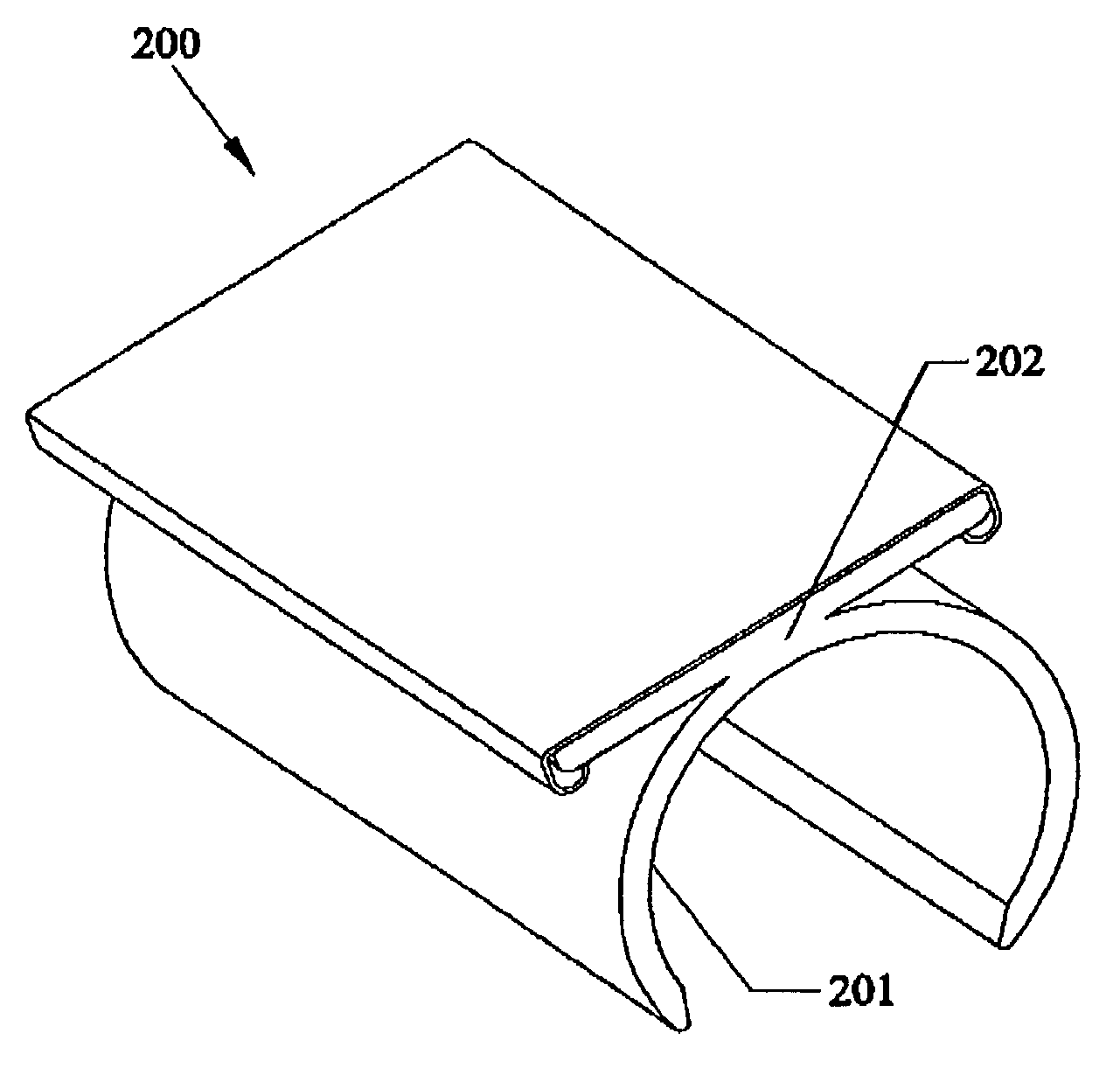
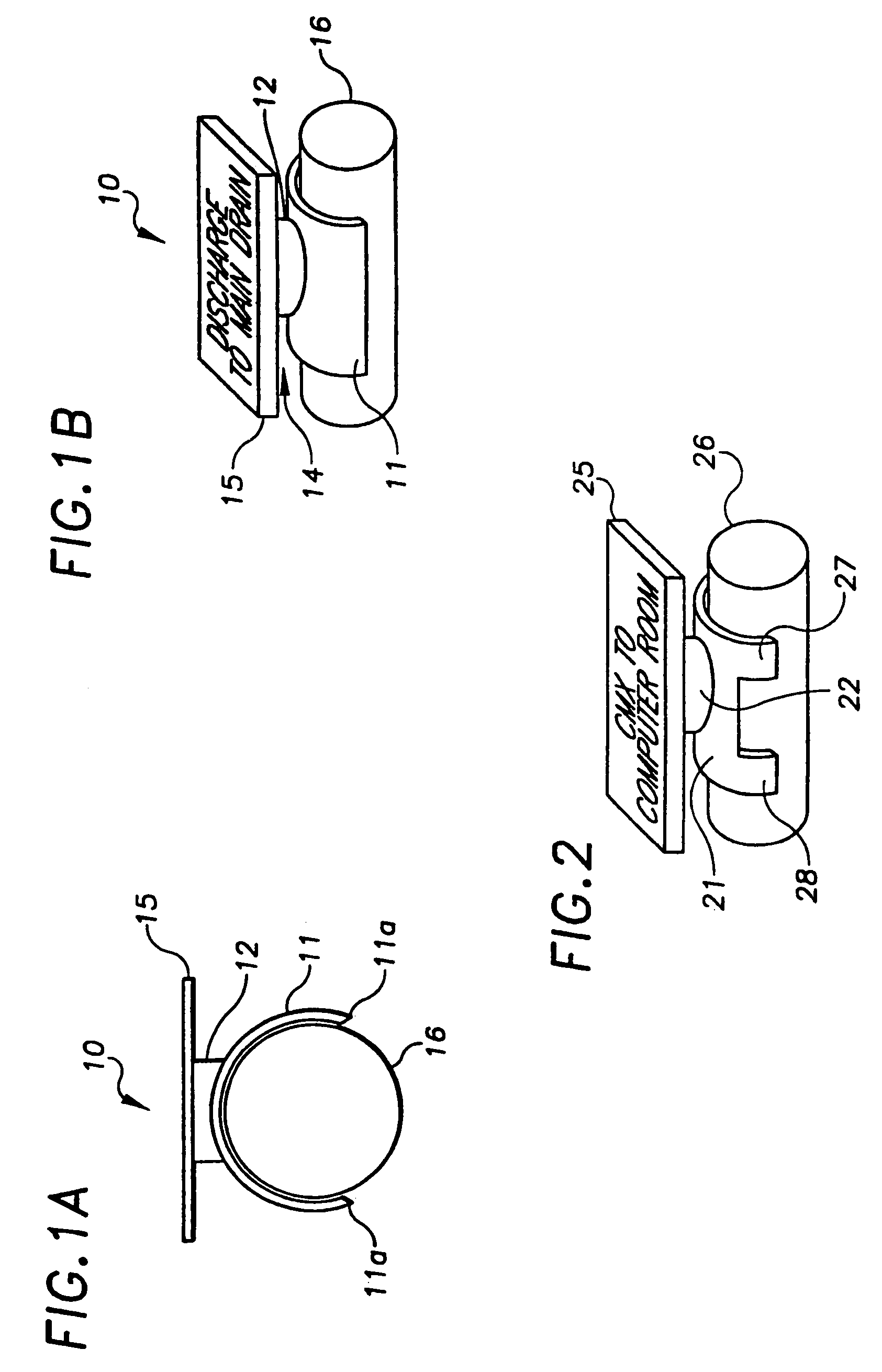
[0037]Referring to FIGS. 1A and 1B, a labeler 10 includes a sign plate 15 permanently molded to a saddle stem 12 which in turn connects to a saddle fitting 11. The inside diameter of saddle fitting 11 is preferably shaped as a section of a circle having a gap of less than 180°, such that when applied to a pipe, tube, or conduit having an outside diameter and an axial length, the inside diameter of the saddle fitting 11 is equal to or slightly smaller than the outside diameter of the pipe, tube or conduit and the inside diameter of the saddle fitting is in contact with the outside diameter of said pipe, tube, or conduit. Sign plate 15 is preferably of a size to allow legible identification of a pipe 16, while being any shape or thickness. Marking of sign plate 15 can be as simple as writing directly on it with a magic marker, or by affixing a computer-produced label, or any other labeling method the user found suitable. For example, the engineers, designers and architects of complex ...
second embodiment
[0046]Referring to FIG. 5A, a second embodiment is shown in which a sign plate 55 of a labeler 50 is slightly adjustable. Sign plate 55 connects to a saddle stem 52 via a movable joint 54. A socket portion 53a of joint 54 optionally includes a plurality of slots (not shown) therein to permit easy connection with a ball portion 53b of joint 54. As with the previously described embodiments, saddle fitting 51 has an inside diameter equal to or slightly smaller than an outside diameter of a pipe 56. Saddle fitting 51 optionally includes one or more saddle legs 57. Joint 54 permits rotation adjustments and slight angling adjustments to be made to sign plate 55.
[0047]Referring to FIG. 5B, a variation of the second embodiment is shown wherein a sign plate 55′ of a labeler 50′ is connected to a saddle fitting 51′ by a ball & knuckle joint 58′ which consists of a knuckle 54′ which fits over a ball 53′. Joint 58′ permits rotation and slight angling adjustments to be made to sign plate 55′. Kn...
third embodiment
[0048]Referring to FIG. 6, the invention is shown which is adjustable. A labeler 60 includes a saddle fitting 61 permanently molded to a saddle stem 62. Saddle fitting 61 optionally includes saddle legs 67, 68, and an inside diameter of saddle fitting 61 and saddle legs 67, 68 is equal to or slightly smaller than a pipe (not shown). A first movable joint 63A connects a first extension arm 64A to saddle stem 62. A second movable joint 63B optionally connects a second extension arm 64B to first extension arm 64A. A third movable joint 63C optionally connects a sign plate 65 to second extension arm 64B. The basic configuration is sign plate 65 connected to first extension arm 64A, either with or without movable joint 63B. Other variations of extension arms and movable joints are possible. The movable joints shown in the figure are ball and knuckle joints, but any movable joint can be used.
[0049]This embodiment allows for maximum flexibility in positioning sign plate 65. This is of use ...
PUM
 Abstract
Description
Claims
Application Information
 - R&D
- Intellectual Property
- Life Sciences
- Materials
- Tech Scout
- Unparalleled Data Quality
- Higher Quality Content
- 60% Fewer Hallucinations
Browse by: Latest US Patents, China's latest patents, Technical Efficacy Thesaurus, Application Domain, Technology Topic, Popular Technical Reports.
© 2025 PatSnap. All rights reserved.Legal|Privacy policy|Modern Slavery Act Transparency Statement|Sitemap|About US| Contact US: help@patsnap.com


